
4 Digit Alarm Keypad
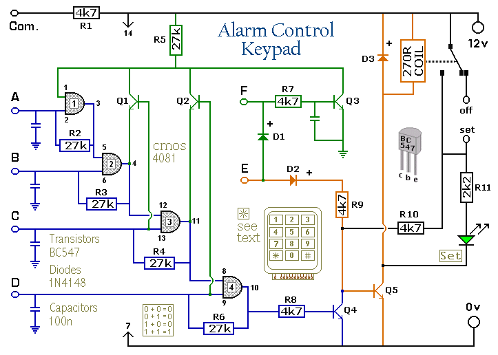
The described circuit utilizes a 12-key keypad configured with a common terminal, which allows for individual connections for each key. This configuration is essential for ensuring that each keypress can be detected independently, facilitating the setting and resetting of an alarm system. The keypad features a total of 13 terminals, with one common terminal connected to a resistor (R1), which serves as the reference point for the keys.
When a specific key is pressed to set the alarm, it is connected to terminal E. This action initiates a current flow through diode D2 and resistor R9, which in turn activates transistor Q5. The activation of Q5 allows for the energization of a relay, which is responsible for switching the alarm system from the "off" state to the "set" state.
To deactivate the alarm, four additional keys must be selected and connected to terminals A, B, C, and D. This feature enhances security by allowing a range of codes, including non-numeric symbols, thus providing over 10,000 possible combinations for user codes.
Once the relay is activated, it maintains its state by providing feedback through resistor R10, ensuring that Q5 remains in the 'on' state even after the initial keypress is released. The circuit also incorporates an LED indicator that illuminates when the alarm is active, providing a visual cue of the system status.
The design of this circuit emphasizes reliability and user-friendly operation, making it suitable for various alarm applications. The careful selection of components and their arrangement ensures that the system is both effective and efficient in its function.The Keypad must be the kind with a common terminal and a separate connection for each key. On a 12-key pad, look for 13 terminals. The matrix type with 7 terminals will NOT do. The Alarm is set by pressing a single key. Choose the key you want to use and wire it to `E`. Choose the four keys you want to use to switch the alarm off, and connect them to `A B C & D`. Your code can include the non-numeric symbols. With a 12-key pad, over 10 000 different codes are available. Wire the common to R1 and all the remaining keys to `F`. When `E` is pressed, current through D2 and R9 switches Q5 on. The relay energises, and then holds itself on by providing base current for Q5 through R10. The 12-volt output is switched from the "off " to the "set " terminal, and the LED lights. To switch the Alarm off again it is necessary to pre 🔗 External reference
Related Circuits
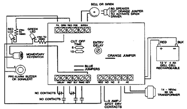
The following alarm circuit is designed with features that may be suitable for residential and commercial alarm system applications. This residential alarm circuit also includes a delay circuit, a 24-hour panic circuit, a built-in siren driver, alarm memory, remote...

A project for a morning or sunrise alarm circuit that generates a beep-beep alarm sound and flashes an LED in response to sunlight. This sunrise alarm circuit is designed to provide a gentle awakening experience by utilizing both auditory and...

This switch is designed for the Modular Burglar Alarm circuit but can be utilized in various other applications. The keypad must feature a common terminal with separate connections for each key. For a 12-key pad, there should be 13...

This circuit will activate in the presence of any fluid that exhibits a resistance lower than 900K ohms, within the maximum separation distance of the probes. The circuit employs a 4050B CMOS hex buffer operating on a 5-volt supply. The...

The circuit diagram illustrates an ultra-sensitive intruder alarm. The mere shadow of an intruder passing within a few meters of the circuit is sufficient to activate the alarm. In this setup, the IC2 uA741 is configured as a sensitive...
This circuit indicates the water level in an overhead tank and activates an alarm when the tank is full. It utilizes the commonly available CD4066 bilateral switch CMOS IC to display the water level through LEDs. When the tank...