
4 Transistor Transmitter
The circuit operates as an FM transmitter, effectively modulating an audio signal onto a high-frequency carrier wave. The Colpitts oscillator serves as the core frequency generation component, where the selection of capacitors and the inductor is crucial for achieving the desired operating frequency. The tank circuit plays a pivotal role in determining the oscillation frequency, and the precise values of the capacitors and inductor must be calculated to ensure the circuit resonates at approximately 100 MHz.
The microphone preamplifier, utilizing the 2N3904 transistors, amplifies the audio signal before it is modulated. The 5 kΩ preset resistor allows for adjustment of the gain, enabling optimization based on the input audio level. This flexibility is essential for adapting to various audio sources.
The modulation process is facilitated by the integration of the 5 pF capacitor and the 10 kΩ resistor, which together with the 1N4002 diode, allow for controlled audio modulation depth. The diode's role is to rectify the signal, ensuring that the modulation does not exceed a certain threshold, thus maintaining signal integrity and preventing distortion.
In the output stage, the Class D amplifier configuration is effective for high-efficiency power amplification. The absence of direct biasing simplifies the design while still allowing the RF signal to drive the output stage effectively. The inclusion of an emitter resistor and a 1 kΩ base resistor is critical for maintaining stability, preventing oscillations that could lead to thermal issues, which is a common concern in high-power RF applications.
Overall, this circuit is a well-designed FM transmitter capable of delivering a robust modulated signal suitable for various applications, including amateur radio and audio broadcasting. Proper attention to component selection and configuration ensures reliable performance and efficient operation.This circuit provides an FM modulated signal with an output power of around 500mW. The input Mic preamp is built around a couple of 2N3904 transistors, audio gain limited by the 5k preset. The oscillator is a colpitts stage, frequency of oscillation governed by the tank circuit made from two 5pF capacitors and the inductor.
( Click here for Colpit t Oscillator Resonant Frequency Equation. ) Frequency is around 100Mhz with values shown. Audio modulation is fed into the tank circuit via the 5p capacitor, the 10k resistor and 1N4002 controlling the amount of modulation. The oscillator output is fed into the 3. 9uH inductor which will have a high impedance at RF frequencies. The output stage operates as a class D amplifier, no direct bias is applied but the RF signal developed across the 3.
9uH inductor is sufficient to drive this stage. The emitter resistor and 1k base resistor prevent instability and thermal runaway in this stage. 🔗 External reference
Related Circuits
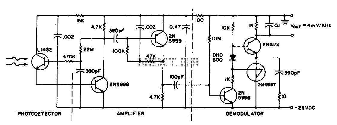
This circuit consists of an L14G2 detector, two stages of gain, and an FM demodulator. Better sensitivity can be obtained using more stages of stabilized gain with automatic gain control (AGC). The circuit design features an L14G2 detector, which serves...
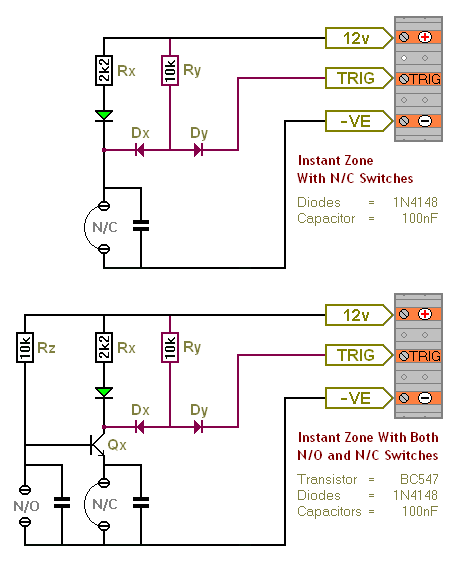
The Transistor Burglar Alarm System allows for the addition of multiple extra zones. The primary circuit is compatible with standard normally-closed input devices, including magnetic reed contacts, micro switches, foil tape, and passive infrared sensors (PIRs). An auxiliary circuit...

The circuit diagram of the Radio Collar Transmitter is presented here. This circuit is based on the NE555 integrated circuit, which serves as the central component. The Radio Collar Transmitter circuit utilizes the NE555 timer IC to generate a modulated...
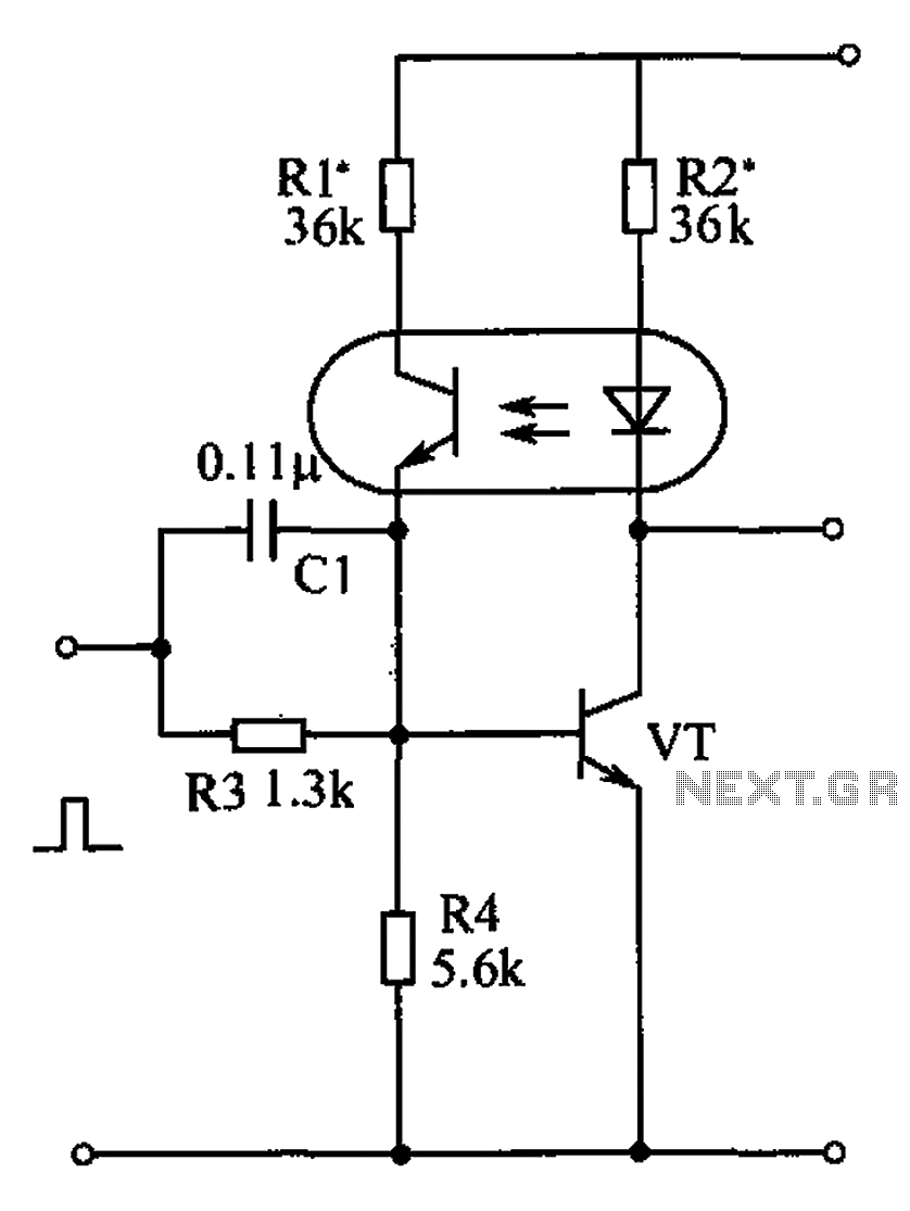
The bistable circuit and optocoupler transistor operate as illustrated in the accompanying figure. Initially, when the supply voltage is applied, the transistor VT is in the off state, resulting in a high output potential. Upon receiving a forward pulse...
This circuit transmits a continuous audio tone on the FM broadcast band (88-108 MHz), which can be utilized for remote control or security applications. The circuit draws approximately 30 mA from a 6-9 volt battery and has a reception...

The 2N2222 circuitry is a three-element, phase-shift oscillator circuit designed to produce a 1,000 Hz sine wave. This sine wave is applied to the TCG-610 varactor diode, which has a capacitance of 6 pF at 4 V. This application...
Warning: include(partials/cookie-banner.php): Failed to open stream: Permission denied in /var/www/html/nextgr/view-circuit.php on line 713
Warning: include(): Failed opening 'partials/cookie-banner.php' for inclusion (include_path='.:/usr/share/php') in /var/www/html/nextgr/view-circuit.php on line 713