
4 X 15 Watt power amplifier
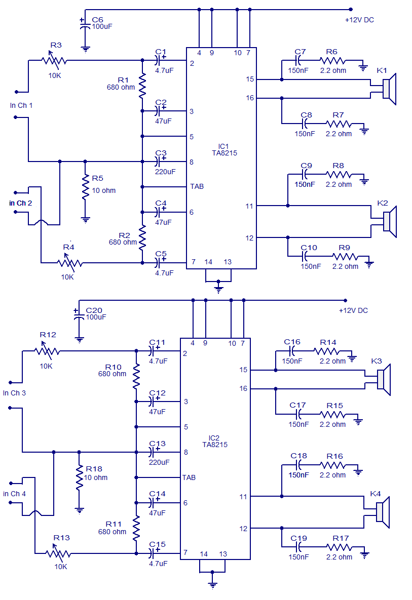
The four-channel audio amplifier circuit utilizes two TA8215 integrated circuits (ICs) to achieve its functionality. Each channel is capable of delivering a power output of 15 watts into a 4-ohm load, making it suitable for driving speakers in diverse audio applications. The choice of a single 12V DC power supply simplifies integration into various environments, particularly automotive audio systems, where such voltage levels are readily available.
The TA8215 IC is designed to operate efficiently in both car and home audio applications, providing flexibility for the end user. The circuit layout closely follows the recommended application diagram from the IC's datasheet, ensuring optimal performance and reliability. The power supply connections are critical; Vcc pins (7 and 19) for the power amplifiers and pin 9 for the preamplifier are connected to the positive supply, ensuring stable operation.
Grounding is meticulously managed within the circuit. The ground pins for the power amplifiers (pins 13 and 14) are connected together and linked to the common ground, while the preamplifier's ground pin (pin 5) is connected to the common ground through a 10-ohm resistor. This resistor creates a separation that is beneficial for noise rejection, a crucial aspect in audio applications to minimize hum and interference.
Decoupling is addressed through the inclusion of a 100µF capacitor, which serves to stabilize the power supply and filter out any high-frequency noise that may be present. The design incorporates resistor networks at the output lines of each amplifier channel to enhance high-frequency stability, ensuring that the amplifier maintains performance across the audio spectrum.
Volume control is facilitated by variable resistors (R3, R4, R12, and R13) for each channel, allowing users to adjust the audio levels according to their preferences. The versatility of this amplifier circuit makes it suitable for a wide range of applications, including car audio systems, home theater setups, personal audio devices, and public address systems, catering to both casual listeners and audio enthusiasts alike.A lot of electronic circuits in the domain of audio amplifiers are already been published here. This circuit is a little different because it is a four channel amplifier. Each channel of this amplifier can deliver an output of 15Watts into a 4 ohm speaker. The amplifier can be operated from a single 12V DC supply and this makes it possible to use this amplifier in car audio applications too. The circuit is based on the 15W BTL X 2 channel audio power amplifier IC TA8215 from Toshiba. Even though chip is specifically designed for car audio applications it can be also used for home audio applications. Two TA8215 ICs are used here in order to obtain a 4 channel amplifier system. The circuit is designed almost exactly as per the application diagram in the ICs datasheet. Pins 7 and 19 are the Vcc pins of the ICs internal integrated power amplifier stages and these pins are connected to the positive supply.
Pin 9 is the Vcc pin for ICs internal preamplifier and it is also connected to the positive supply. Pins 13 and 14 are the internal power amplifiers ground pins and they are tied together and connected to the ground. The internal preamplifier`s ground pin (pin5) is connected to the common ground through a 10 Ohm resistor which makes the input ground separated from the common ground by a resistance of 10 ohms and this improves the noise rejection.
The 100uF capacitor works as a power supply de-coupler. The resistor networks connected to the output lines of each amplifier improves the high frequency stability. The variable resistors (R3, R4, R12 and R13) works as the volume controller for the corresponding channels.
This amplifier circuit can be used in a variety of applications such as car audio systems, home theater systems, personal audio systems, public address systems etc. 🔗 External reference
Related Circuits
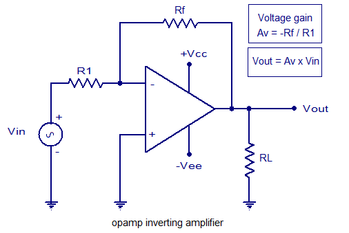
An inverting amplifier utilizing an operational amplifier (op-amp). This includes equations for voltage gain and output voltage, as well as input and output waveforms, and a practical inverting amplifier circuit using the 741 IC. An inverting amplifier is a fundamental...
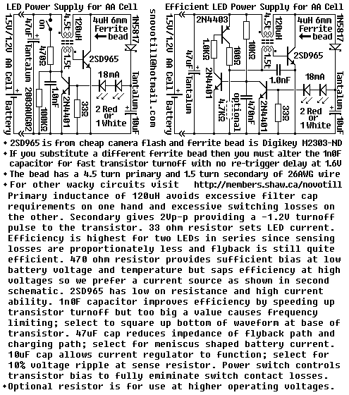
Efficiency can be increased by using a germanium transistor at the 33 ohm current sense resistor, and by using a proper torroid core in place of the crappy ferrite bead. Single AA cell powers two LEDs at constant current. The...
This circuit greatly expands upon the capabilities of circuit 02. A thermocouple signal is quite small, and the long thermocouple leads often induce quite a bit of noise into the system. This new circuit is far more accurate, stable,...

Another method of using opamps to regulate a power supply is shown below. The power transformer requires an additional winding to supply the op-amps with a bipolar voltage (+/- 8 volts), and the negative voltage is also used to...

10W audio amplifier with bass boost. High quality, very simple design. No preamplifier required. Circuit diagram: Parts: P1 22K logarithmic potentiometer (dual-gang). This audio amplifier circuit is designed to deliver a power output of 10 watts, making it suitable for...
This is a low-cost project for 20 or 40 watt fluorescent tubes. However, the most efficient is to use a 40 watt tube (or two 20 watt tubes in series). It's a circuit you can put together from junk...