
dc motor control pwm 555
The described circuit employs a 555 timer IC configured in astable mode to generate a pulse-width modulation (PWM) signal. The frequency and duty cycle of the PWM signal can be adjusted by varying the resistor and capacitor values connected to the 555 timer. This modulation allows for precise control over the average voltage supplied to the DC motor, effectively adjusting its speed.
Key components of the circuit include the 555 timer IC, a potentiometer for adjusting the resistance, and a capacitor to set the timing intervals. The motor is connected to the output of the 555 timer through a transistor, which acts as a switch to handle the higher current required by the motor. Additional components may include diodes for flyback protection, ensuring that voltage spikes generated by the motor when it is turned off do not damage the circuit.
The schematic layout typically features the 555 timer IC at the center, with connections to the potentiometer and capacitor forming the timing circuit. The output pin of the 555 timer connects to the base of the transistor, which is used to control the motor. A power source is connected to the motor and the transistor's collector, while the emitter is grounded.
This PWM circuit is not only efficient but also minimizes heat generation compared to linear control methods, making it suitable for various applications where speed control of DC motors is necessary. The simplicity of the circuit allows for easy integration into larger systems or for educational purposes in understanding motor control techniques.This simple DC motor control or PWM circuit using 555 IC can be used to control the speed of a DC motor. The circuit is very simple and can be built in very short time if all parts are available with you.. 🔗 External reference
Related Circuits
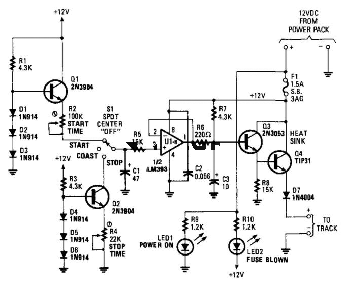
The unique aspect of this control is its momentum feature, which enhances realism. The circuit is designed to operate efficiently for trains that draw up to 1 A at 15 V. None of the components are critical. In the...
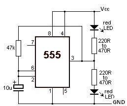
This LED flasher circuit utilizes the 555 timer integrated circuit (IC). The circuit diagram is straightforward and requires only a few external components. When operational, the red LEDs will flash sequentially at a predetermined frequency, similar to the indicators...
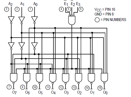
The Motorola SN54/74LS138 is recognized as a 1-of-8 decoder or demultiplexer, specifically engineered for high-speed bar memory chip select address decoding. The accompanying diagram illustrates the logic configuration of the SN54/74LS138 demultiplexer. According to the SN54 datasheet, the multiple...
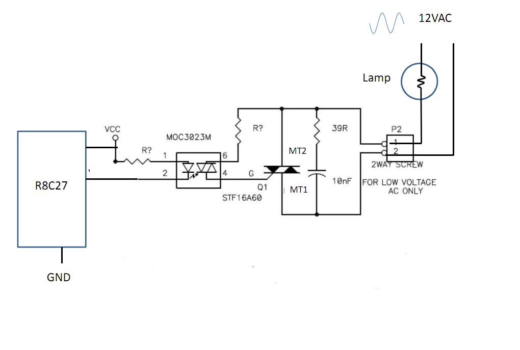
Control 30 incandescent light bulbs with an Arduino Uno on three channels (10 bulbs per channel in parallel). Previous experience involved using an Arduino to control red, green, and blue LEDs with a simple schematic that included three transistors....
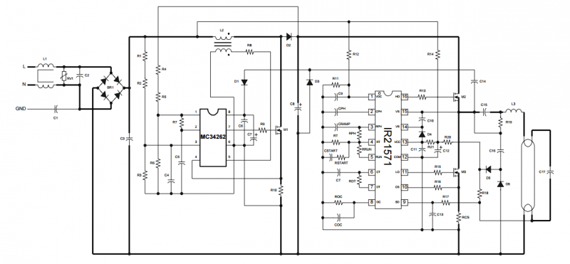
The IRPLLNR2 is a high efficiency, high power factor, fixed output electronic ballast designed for driving rapid start fluorescent lamp types. The design contains an EMI filter, active power factor correction and a ballast control circuit using the IR21571....
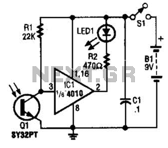
The IR Tester circuit indicates whether the button pressed on a remote control is functioning. Q1 is a phototransistor that is activated by infrared (IR) energy. The IR Tester circuit operates by detecting infrared signals emitted by remote control devices...