
Metal detector using 555
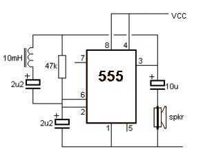
The metal detector circuit utilizes the 555 timer IC in an astable mode configuration, which allows it to produce a continuous square wave output. The frequency of this output is influenced by the presence of metal or magnets in proximity to the sensing coil (L1). The circuit includes a choke of 10mH, which serves as an inductor that, in combination with the coil, creates a resonant circuit.
When a metal object is detected, the inductance of the coil changes, which in turn alters the oscillation frequency produced by the 555 timer. This change in frequency is significant enough to be detected by the circuit and is used to drive an 8-ohm speaker, producing an audible sound as a response to the detected metal.
The power supply for this circuit must provide a stable DC voltage in the range of 6 to 12 volts. This allows for flexibility in the choice of the power source, whether it be batteries or an external power adapter. The simplicity of the design, requiring only a few external components such as resistors, capacitors, the choke, and the speaker, makes it an accessible project for beginners in electronics.
The circuit can be further enhanced with additional features, such as sensitivity adjustments or visual indicators (like LEDs), to improve the user experience. However, the fundamental operation relies on the interaction between the 555 timer, the inductor, and the detection of metal through changes in oscillation frequency.A very simple metal detector electronic project can be designed using a simple 555 timer integrated circuit . As you can see in the schematic circuit , this electronic project requires few external electronic parts .
This circuit detects metal and also magnets. When a magnet is brought close to the 10mH choke, the output frequency changes. This metal detector project can be powered from a power supply that can provide an output DC voltage between 6 an 12 volt . If a metal is closer to the L1 coil , will produce a change of output oscillation frequency, that will generate a sound in the 8 ohms speaker .
🔗 External reference
Related Circuits
This ring generator will ring a telephone once every 10 seconds. The interval between rings can be lengthened or shortened by varying the value of the 1 Meg resistor. The 70 volt/ 30 Hz ring voltage is produced from...
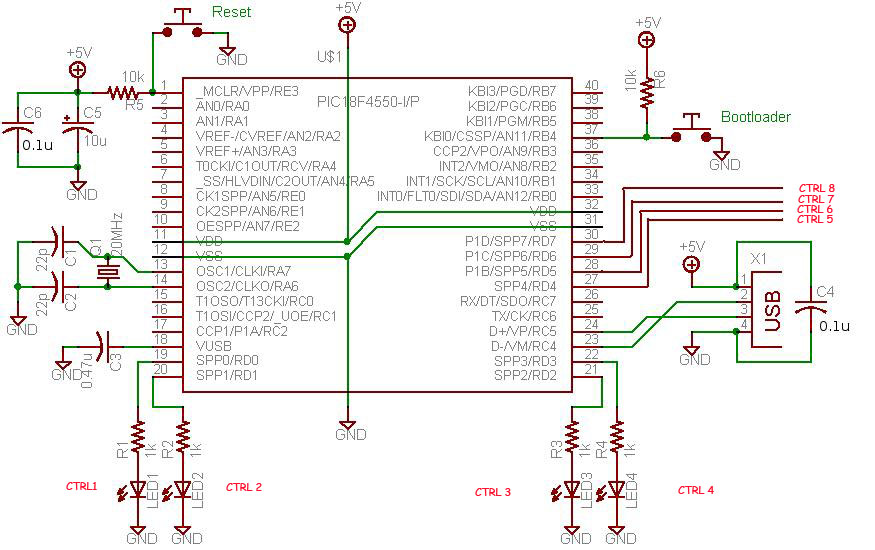
This project demonstrates a computer control interface using a USB board (USB Interface Project). This tutorial provides a straightforward method to control devices such as LEDs, motors, and other components via a computer using a USB board. Traditionally, devices...
Free-space optical (FSO) communication utilizes light as a medium for data transmission. Communication was established between two computers using a laser, independent of any conventional communication methods. Text messages were sent from one PC to another using a system...

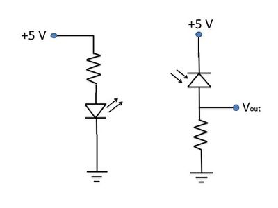
This is a light sensor circuit designed to detect darkness, utilizing the op-amp 741 integrated circuit as the primary control element. The circuit is straightforward and specifically designed to sense light during nighttime. The light detection is accomplished using...
This photocell is best mounted at tie level between the rails. The variable resistor adjusts the sensitivity of the circuit. This circuit can be powered by either 6 or 12 volts - BE SURE to use the proper relay;...
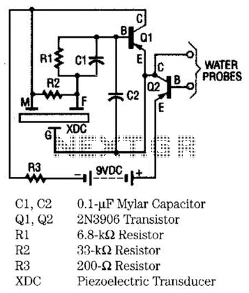
The moisture detector utilizes two transistors and a piezoelectric transducer to emit an alarm tone when water is detected. Transistor Q1 functions as a crystal-controlled oscillator, employing a portion of the piezoelectric transducer XDC, which consists of two piezoelectric...
Warning: include(partials/cookie-banner.php): Failed to open stream: Permission denied in /var/www/html/nextgr/view-circuit.php on line 713
Warning: include(): Failed opening 'partials/cookie-banner.php' for inclusion (include_path='.:/usr/share/php') in /var/www/html/nextgr/view-circuit.php on line 713