
40 m Band Direct Conversion Receiver

The design of a direct conversion receiver for the 40 m CW band necessitates careful consideration of signal integrity and dynamic range, especially due to the proximity of strong signals from adjacent frequency bands, such as the 41 m band. To mitigate the risk of overload from these strong signals, a diode-ring mixer is employed in the circuit architecture. This type of mixer is known for its superior performance in terms of linearity and dynamic range compared to integrated circuit (IC) mixers.
The diode-ring mixer operates by utilizing a ring of diodes to perform the mixing process, allowing for efficient signal conversion while maintaining low distortion levels. This is crucial when dealing with high signal levels that can typically saturate other mixer types. The choice of diodes, their configuration, and the biasing conditions are essential parameters that influence the mixer’s performance.
In conjunction with the diode-ring mixer, a narrow band RF input filter is incorporated into the design. This filter serves to attenuate out-of-band signals that may interfere with the desired CW signal, further enhancing the overall selectivity and sensitivity of the receiver. The filter should be designed to have a bandwidth that matches the characteristics of CW signals while ensuring that it effectively suppresses the adjacent 41 m band signals.
The overall receiver architecture should also include additional components such as low-noise amplifiers (LNAs), local oscillators (LOs), and appropriate power supply arrangements to ensure stable operation across varying conditions. The combination of these elements results in a direct conversion receiver that not only achieves a practical and usable design for the 40 m CW band but also provides a significant improvement in dynamic range compared to traditional IC mixer solutions, such as the NE612.
Careful attention to layout, component selection, and tuning will be necessary to realize the full potential of this receiver design, ensuring that it meets the demands of amateur radio operators seeking high-performance communication capabilities in the crowded 40 m band.Building a practical and usable direct conversion receiver for the 40 m CW band is not as simple as it might appear. Broadcast station signals from the adjacent 41 m band, will easily overload most direct conversion mixer designs with their unwanted (and quite nearby) S9 +40 dB signals.
My solution incorporates a diode-ring mixer and a narrow band rf input filter. These choices result in observed overall receiver dynamic range than that experienced when using an IC mixer module (such as a NE612). 🔗 External reference
Related Circuits
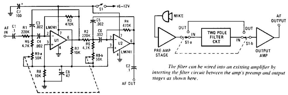
This variable-frequency audio bandpass filter is constructed using two 741 operational amplifiers connected in cascade. The two 741 op amps are configured as identical RC active filters and are cascaded to enhance selectivity. The filter's tuning range spans from...
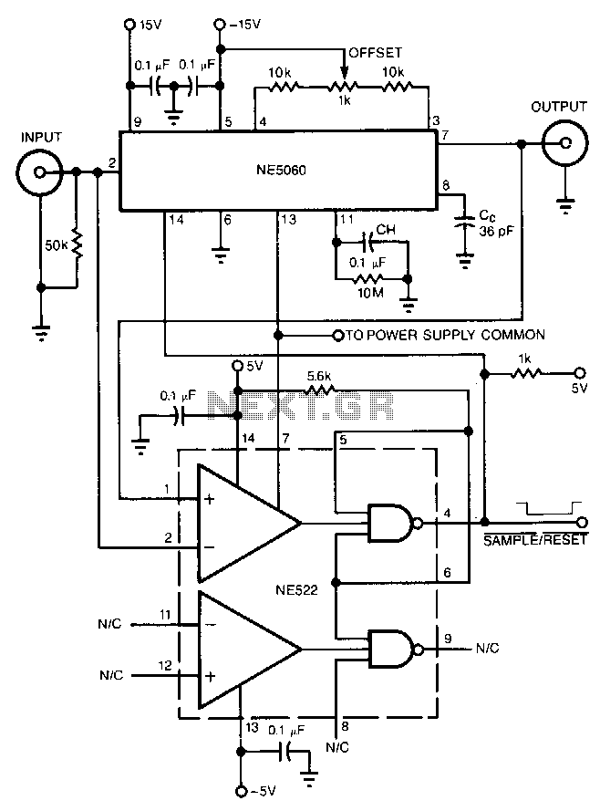
The high-speed peak detector utilizes a highly accurate, fast sample-and-hold (s/h) amplifier that is controlled by a high-speed comparator. The s/h amplifier retains the peak voltage until the comparator switches the amplifier to its sample mode to capture a...
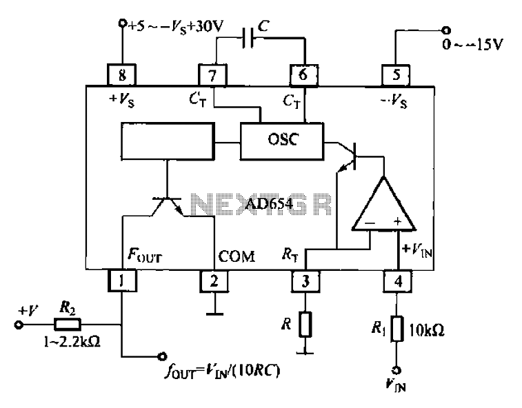
The AD654 voltage-frequency converter is a low-cost device that operates with a single supply voltage ranging from +5V to +36V, as well as with dual supplies of +5V to +18V. It can handle a maximum input voltage of 36V...
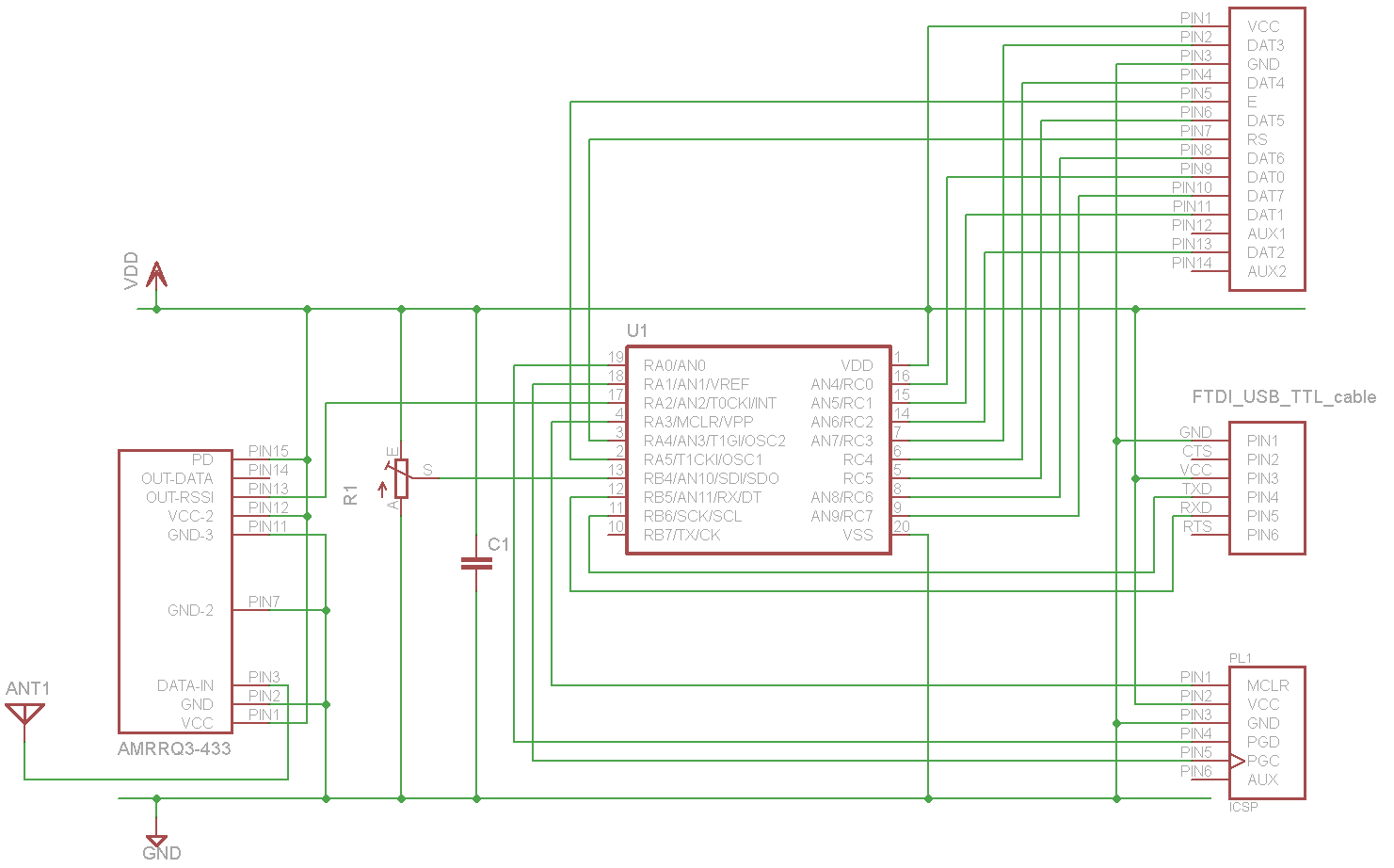
A sensor project that transmits its measurements via a 433 MHz wireless communication link. This document describes the details of a self-built receiver designed to receive data from this sensor. The objective is to create a general-purpose RF receiver...
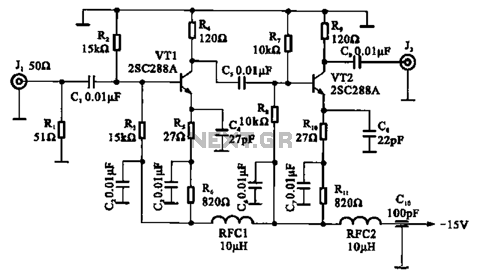
A wideband high-frequency amplifier circuit is presented, utilizing resistance and capacitance coupling in a common emitter configuration to amplify high-frequency signals. When a high-frequency signal with an input impedance of 50 ohms is applied to the amplifier through a...
This is a preselector circuit designed for shortwave (SW) receivers, specifically a do-it-yourself (DIY) high-frequency preselector. The circuit employs a modern low-capacitance MOSFET with two gates, which generates a negative inverse reaction through an uncoupled source resistor. When applied...