
General purpose RF receiver
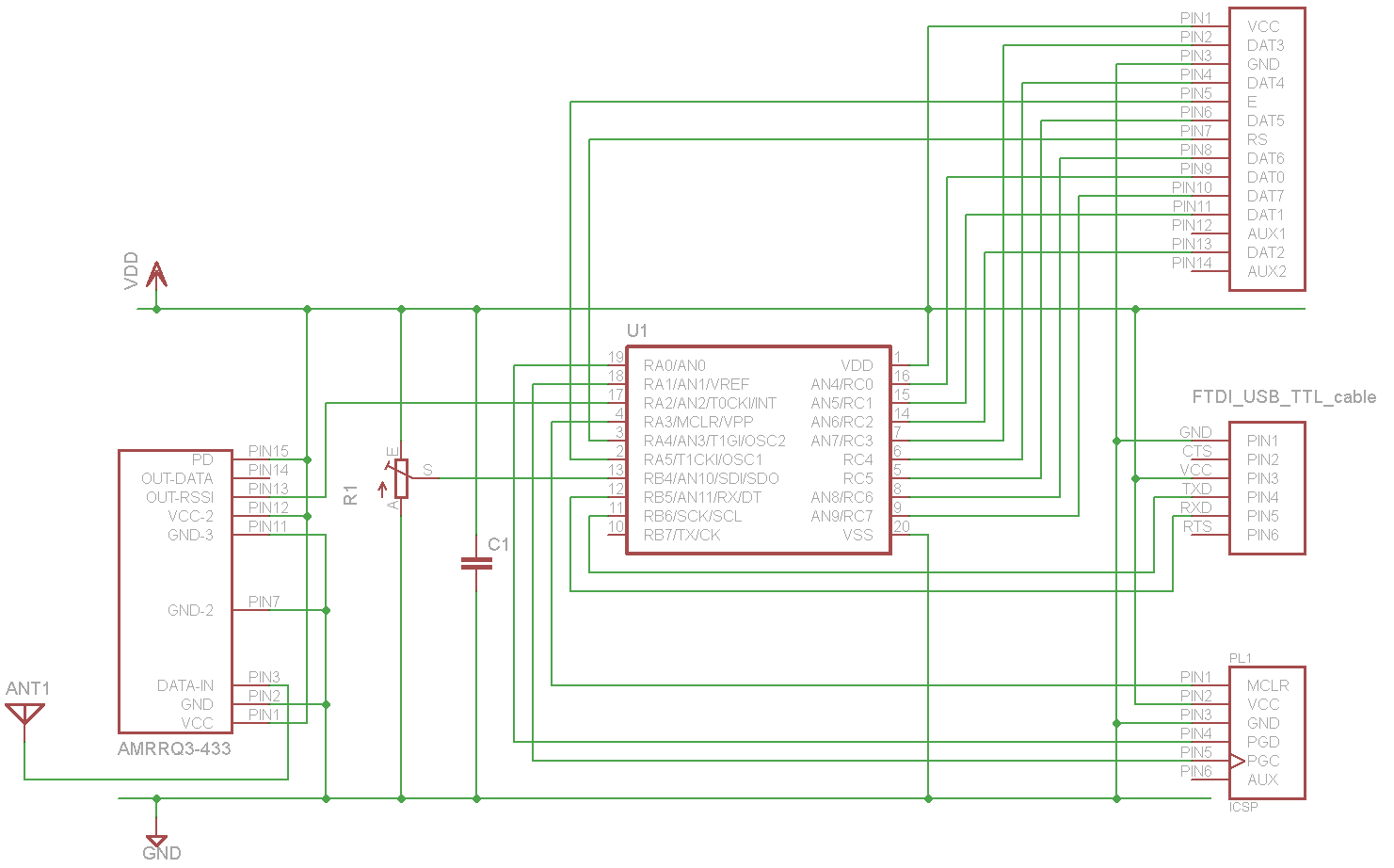
The RF receiver module is designed to operate within a 433 MHz frequency range, suitable for various wireless sensor applications. The integration of the FTDI TTL-to-USB cable simplifies the communication process with the Linux server, allowing for seamless data transfer and processing. The PIC16F690 microcontroller is chosen for its versatility and built-in capabilities, making it ideal for handling the various interfaces required for this project.
The use of the RSSI port for signal reception is a notable feature, as it allows for a more robust detection of valid signals by measuring the strength of incoming RF signals. This capability is essential in environments with potential interference and noise. The configuration of the reference voltage adds an additional layer of flexibility, enabling adjustments based on specific application needs or environmental conditions.
The implementation of the Manchester encoding decoder using a finite-state machine is a sophisticated approach to signal processing, ensuring accurate interpretation of the transmitted data. This method provides resilience against timing variations and signal distortions that may occur during transmission. Overall, this sensor project exemplifies a comprehensive approach to wireless communication, integrating hardware and software components to achieve reliable data transmission and processing.A sensor project which transmits it`s measurements via a 433Mhz wireless communication link. On this page I will describe the details of my self built receiver which receives data from this sensor. To build a general purpose RF receiver module which receives messages from a 433 Mhz wireless link (for example from my self built RF sensor )and forward the received and decoded message to my
Linux server via USB, where they are further processed. For the USB interface, I`ll be FTDI`s TTL-to-USB cable, which is a ready-to-use solution for briding 5V TTL signals to RS232 emulation over USB. This enables the microcontroller talk directly to the linux box without any additional components. The linux kernel supports the FTDI chip, so it works out of the box. When this cable is plugged in, the RS232 port is reachable via /dev/ttyUSB0. For debugging purposes and possible other future features, the receiver module will be able to write to a HD44780 compatible display (I`ll be using the EAW162B-N3LW) which is attached using a 14 channel flat cable For the main processor, a PIC16F690 microcontroller will be used, which has a built-in crystal/clock and enough pins to support all interfaces described above.
For re-programming the firmware of the microcontroller without needing to remove the chip from the board, I`ll be using ICSP (In-Circuit Serial Programming) All messages which this receiver module should be able to receive are encoded in my own RF protocol. This protocol is a kind of Ethernet protocol, it contains a destination address field, a source address field a message length and a checksum field.
This protocol does not say anything about the kind of content which it carries. The syntax looks as follows: When transmitted over RF; the message is encoded using Manchester encoding which is a self-clocking signal where each bit is actually sent using two bits. The length of a low-level bit is 0. 5 ms which means that each logical bit takes 1 ms to transmit. At the beginning of each message, there is a start bit sent with the value of HIGH for 0. 5ms. The hardest part of this project was to translate the raw signal, which the AM-RRQ3-433 provides, to a usable message and disregard any noice and foreign signals.
The main idea here is that the RSSI port of the AM-RRQ3-433 module is used directly as a signal source (instead of the DATA-OUT port). The RSSI port is an analog port which provides both signal strength information and the information in the signal itself, whereas the DATA-OUT port is a digital port and only provides the digital signal received via RF.
The DATA-OUT port will raise to HIGH (=5V) on the slightest noice on the RF channel, while the RSSI port will output a voltage which tells us about how strong the receive signal actually is. So by measuring the output voltage of the RSSI port using AD (analog-digital conversion), it is possible to both receive the signal itself and also the strength of this signal.
So when the microcontroller is receiving a signal from the RF module, a configurable reference voltage provides the minimum required voltage (signal strength) which the RSSI port has to output in order for the microcontroller to recognize this as a HIGH (1). Any voltages which the RSSI port outputs which are below this configurable reference voltage are seen as a LOW (0) by the microcontroller.
The next step after this noice filtering is to translate the received HIGH`s and LOW`s into a understandable message. In the attached source code, I`ve implemented a decoder for manchester encoding which is based on the finite-state-machine concept.
A state machine is ideal to keep track of the current received bit and to determine which is the next expected next bit. As soon as a mismatch is found, a bit lasts too long (timeout case) or the max message length is exceeded, the state machine goes into error state and further reading is
🔗 External reference
Related Circuits
This circuit requires physical connections to be made to the computer's serial port (COM1 or COM2). It is generally considered difficult to cause harm to oneself or the computer through improper connections to this port; however, there is no...
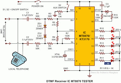
Most telephone equipment today utilizes a DTMF receiver integrated circuit (IC). A widely used DTMF receiver IC is the Motorola MT8870, which consists of 18 pins and is employed in telephones and various other applications. When projects utilizing this...

The integrated circuit U1, which is an NE602 double-balanced mixer, functions as both an oscillator and a frequency mixer. Signals received from the antenna input at J1 are transmitted through a DC-blocking capacitor C1 to the RF-gain control resistor...
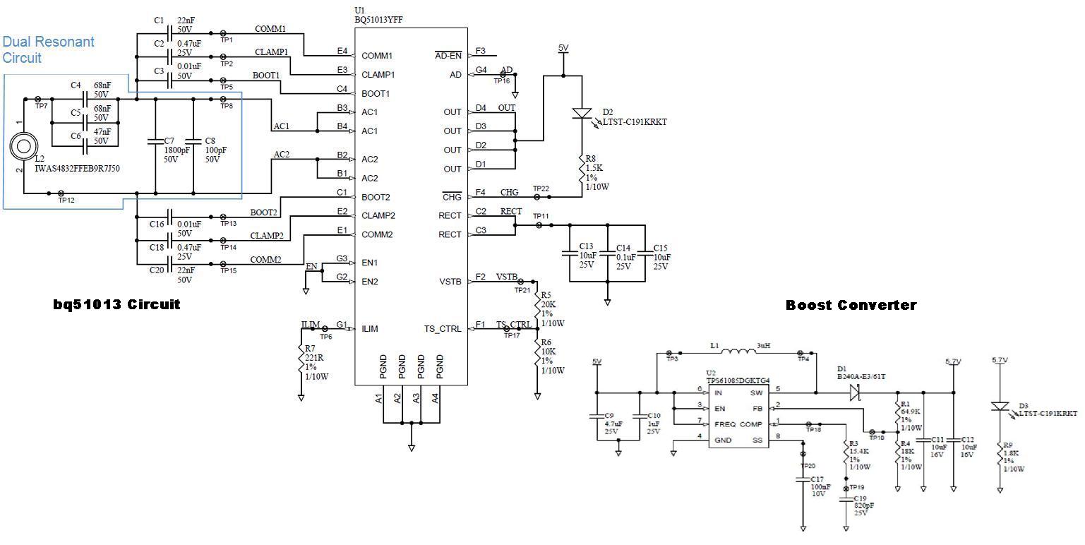
Several boards have been constructed using the bq51013 EVM receiver circuit along with a TPS61085 boost converter circuit, designed in SwitcherPRO Design Software, to elevate the voltage level to 5.7 volts. However, when a load of 580 mA, required...

The induction receiver described is highly sensitive and versatile, suitable for various applications including tracing wiring behind walls, receiving audio from an induction transmitter, detecting lightning and other electrical discharges, and monitoring devices that produce an audio magnetic field,...
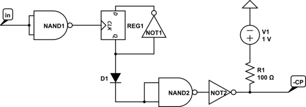
This text discusses the functionality of a flip-flop, specifically focusing on the role of two NAND gates and the presence of an additional inverter. It suggests allowing time for others to analyze the question and formulate their theories, emphasizing...