
40 m Band Superhet Receiver

The circuit design includes several key components that enhance its performance. The first oscillator utilizes a Colpitts configuration, which is known for its stability and ability to generate a precise frequency. The ceramic resonator's broader tuning range allows for slight frequency adjustments without compromising stability, making it ideal for the application. The front-end filter, while not perfect, provides sufficient attenuation of unwanted signals, ensuring that the desired signals are more easily discernible.
The use of the NE592 broadband amplifier in the IF stage is crucial for maintaining signal integrity and selectivity. The addition of a crystal filter significantly enhances the selectivity of the receiver, allowing it to isolate signals within a narrow bandwidth of 200 Hz, which is particularly advantageous for CW operations. The design of the second mixer as a product detector further ensures that only the desired audio frequencies are amplified, while any residual RF signals are effectively filtered out.
The audio amplification stage, utilizing the NE5532, is designed to deliver a high gain while maintaining low output resistance, making it compatible with standard headphones. The volume control mechanism allows for easy adjustment of the audio output, providing user flexibility. Overall, this superheterodyne receiver design is characterized by its simplicity, effectiveness, and adaptability, making it a valuable tool for amateur radio enthusiasts.By the addition of one integrated circuit and some passive components, I was able to convert my earlier developed 40-meter direct conversion receiver design into a superhet model. Anyone who has listened to 40 meters during the evening hours on the crowded 40 m band will appreciate the advantages of the single signal reception, which this circuit
offers. All simple direct conversion receiver designs suffer from degraded selectivity performance and are more subject to overload by contrasted to even modest superhet designs. Direct conversion designs are simpler by contrast because they are missing an IF stage and any associated filtering, a BFO and the second mixer.
In order to modify the design to create a superhet model, it was necessary to increase the 1st oscillator frequency from 7000 kHz - 7040 kHz to a revised range of 10686 kHz -10731 kHz (operating frequency plus the intermediate frequency). The choice of this 1st oscillator frequency turned out to be fairly easy by considering the availability of 3686 kHz crystals.
Bandwidth is set to 200 Hz by a series coupled filter (using a single 3686 kHz crystal) in the IF amplifier section. This choice is highly suitable for CW operation. The choice of 3686 kHz IF allows use of readily available 10. 7 mHz ceramic resonator in the 1st oscillator circuit. The first part of the circuit to be described is the 1st oscillator (main tuning). It is a variation of the Colpitts type oscillator. It uses a 10, 7 ceramic resonator as its frequency-determining component. Unlike a quartz crystal based VXO, the ceramic resonator Q1 results in a much broader tuning range (approximately 45 kHz) while still maintaining a desired level of frequency stability at the same time.
A second ceramic resonator with a center frequency of 7020 kHz is used as a front-end filter. This effectively attenuates much of the strong S9 +40 dB strong signal interference from the 41-meter shortwave broadcast band. The shape factor and center frequency, while not a perfect choice, perform quite well. The stop band for this resonator appears to be located at 7125 kHz - well beyond the desired 7040 kHz.
The availability, low price, simplicity of the circuit and absence of alignment warrant suggest inclusion of this specific device. A network formed by L1 and L2 help match the 330 ohms resonator impedance to the 50 ohms of the diode ring mixer and the antenna.
The output of the ring diode mixer is coupled to an IF stage based on the NE592 broadband amplifier. I was able to narrow the IF selectivity to 200 Hz by adding a crystal filter using series interstage coupling (formed by a 3686 MHz quartz and resistor R8) between pins 2 and 7. The mixer sees at its IF port a parallel circuit consisting out of R7 and the high input impedance of IC1.
L3 and C9 form a parallel resonant circuit that is tuned to the IF. The value of C9 is not critical because the output resistance of IC1 causes strong damping. The second mixer based on the well-known NE612 and is used as a product detector. The mixer output pins of the NE612 drive the differential input of the NE5532 audio amplifier. Any remaining RF energy present at the output pins is shunted to ground by using the two capacitors C14 and C15. These effectively couple only an AF signal output from the product detector stage into the audio amplifier.
The AF stage has a gain of 60 dB at the 750 Hz audio filter center frequency. The audio filter center frequency is determined by the component values used in the passive series resonant circuit formed by Dr1 and C16. The audio output volume adjustment is controlled with an RF attenuator control P1, located close to the antenna input.
The NE5532 output resistance is relatively low, so 60 Ohms headphones can be used without an additional series resistor. The receiver operates well across a wide range of supply voltages ranging from 9 V to 15 V. The AF amplifier is directly powered 🔗 External reference
Related Circuits
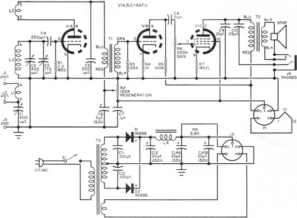
RF Cafe visitor David M. requested the scanning and posting of an article from the January 1963 edition of Popular Electronics, authored by Philip Hatfield from the Receiving Tube Department of General Electric. The article describes a straightforward design...
Electronics tutorial about active band-pass filters, including band-pass filter frequency response, its resonant frequency, and second-order response. Active band-pass filters are essential components in various electronic applications, particularly in signal processing, audio engineering, and communications. These filters are designed to...
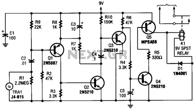
A GC Electronics P/N J4-815 transducer is utilized to receive 40-kHz acoustic remote-control signals. The receiver activates a relay to control another circuit. The GC Electronics P/N J4-815 transducer is designed specifically for the reception of 40-kHz acoustic signals, which...
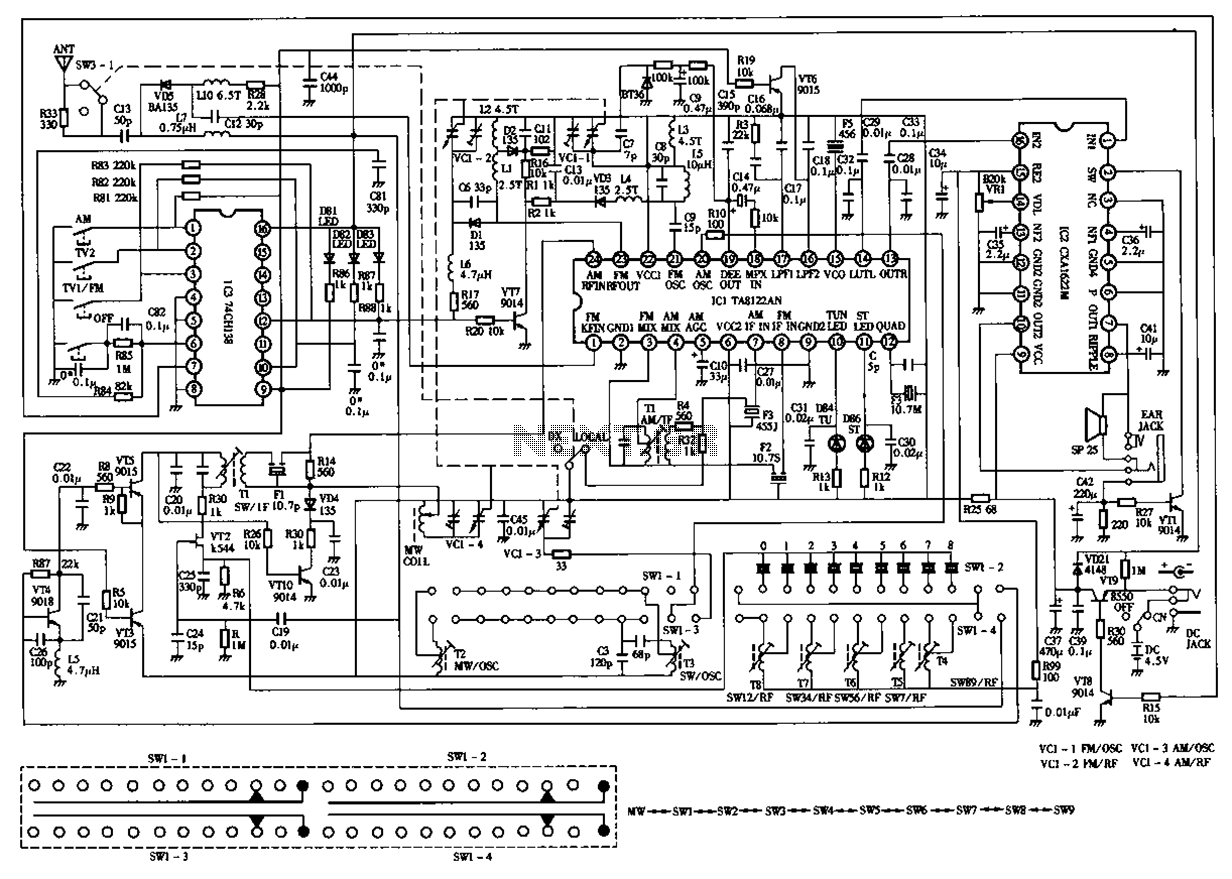
The circuit diagram for the Desheng 119 700 type FM, TV sound, medium wave, and short wave high sensitivity L2-band stereo radio is presented below. The Desheng 119 700 type radio circuit is designed to receive various frequency bands including...
The theory of operation has been previously discussed in the Simple Superhet or the All American Five. Constructing this radio is relatively straightforward, especially if the circuits have been followed in the order presented. The variable capacitor used is...
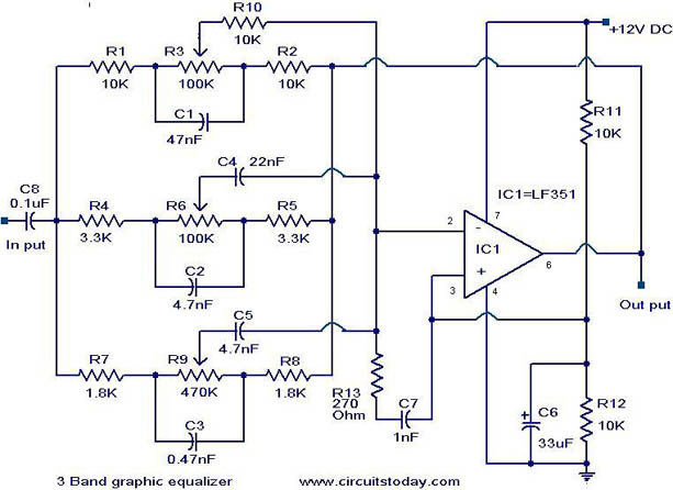
A simple three-band graphic equalizer circuit is constructed using a single op-amp IC, the LF351 (IC1), along with several passive components. The component values in this circuit are not highly critical, allowing for substitutions with nearby values that result...