
Ultrasonic Remote Control Receiver Circuit

The GC Electronics P/N J4-815 transducer is designed specifically for the reception of 40-kHz acoustic signals, which are commonly used in remote control applications. This transducer operates by converting sound waves at the specified frequency into electrical signals, enabling it to detect commands sent from a remote transmitter.
The output from the transducer is processed by a receiver circuit that amplifies the incoming signals and filters out any noise or interference. Once the signal is successfully decoded, the receiver activates a relay. This relay serves as an electromechanical switch, allowing the control of a separate circuit based on the received acoustic signals.
The relay can be used to control various devices, such as motors, lights, or other electronic systems, providing a versatile solution for remote operation. Proper design considerations must be taken into account, including the relay's specifications, such as its voltage and current ratings, to ensure compatibility with the controlled circuit. Additionally, the layout of the circuit should minimize interference and optimize signal integrity for reliable operation in practical applications.
In summary, the GC Electronics P/N J4-815 transducer is a critical component in systems requiring remote control functionality, enabling efficient communication and control through acoustic signals. A GC Electronics P/N J4-815 transducer is used to receive 40-kHz acoustic remote-control signals. The receiver drives a relay for control of another circuit.
Related Circuits
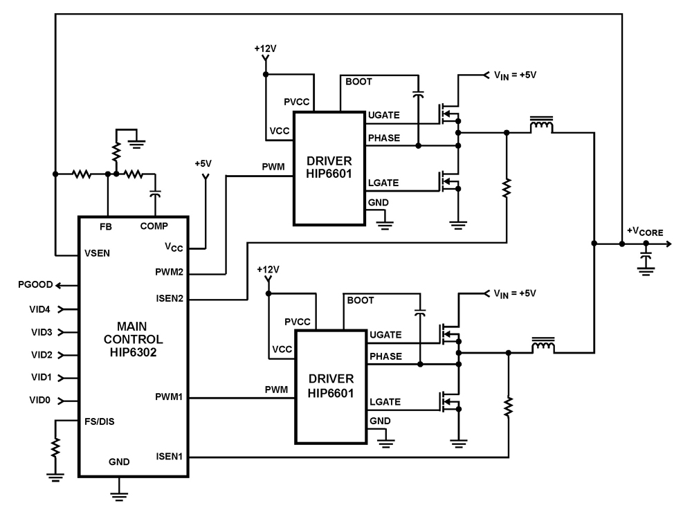
The HIP6302 Multiphase PWM control IC, along with its companion gate drivers (HIP6601, HIP6602, or HIP6603) and Intersil MOSFETs, delivers a precise voltage regulation system for advanced microprocessors. Multiphase power conversion represents a significant advancement over traditional single-phase converter...

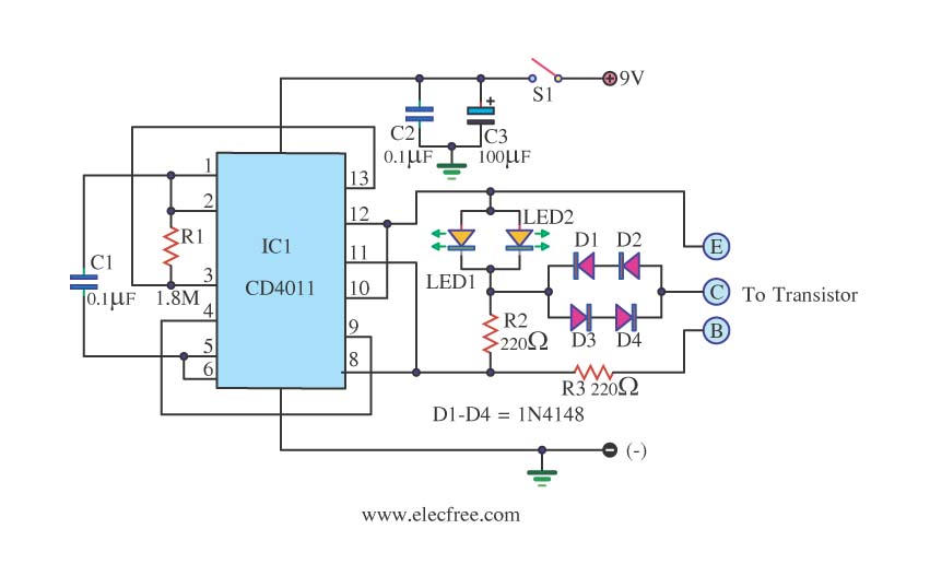
This circuit is designed as a 10-channel LED sequencer with the addition of solid-state relays for controlling AC lamps. The circuit operates using relays. The relay depicted in the diagram is a Radio Shack 3 amp unit (part no....
This is a transistor tester integrated into a circuit or printed circuit board (PCB). It is utilized when a project does not function correctly, allowing for the testing of electronic components. The transistor tester is a crucial tool in electronic...

Fast rise-time high-voltage pulses have various applications, including EMC testing and device characterization. The circuit outlined here is a simple, cost-effective solution designed for the latter purpose. It can generate pulses ranging from 0 to 1000 V with currents...
This receiver operates within the frequency range of 8.5 to 11.5 MHz across two distinct bands and exhibits a sensitivity level of less than 1 µV. The NE602 mixer is utilized to feed a 455 kHz intermediate frequency (IF)...
This device, available in a Stainless DIL 8 package, is capable of measuring four independent analog voltages ranging from 0 to 5 volts. It transmits the measurement results as four characters via a standard asynchronous serial link. The described device...