
4 Tube Superhet
The construction of this radio involves several critical components and steps to ensure proper functionality and alignment. The variable capacitor serves as the heart of the tuning mechanism, enabling the selection of desired frequencies. The choice of a three-section capacitor allows for fine-tuning across the AM band, although the ideal configuration would include a smaller section for optimal performance. The use of trimmer capacitors allows for precise adjustments, which is essential for achieving the best reception quality.
The antenna coil design is key to the radio's ability to pick up signals effectively. The simplification to a single coil design with 66 turns is a practical approach that balances performance with ease of construction. The oscillator coil's adjustment to 40 turns, along with the incorporation of trimmer and padder capacitors, highlights the importance of alignment in radio circuits. The alignment procedure, which involves the use of a frequency counter and signal generator, is a critical step that ensures the radio operates at the correct frequency, maximizing its ability to receive signals.
In summary, the detailed steps and components outlined in this construction guide provide a comprehensive framework for building and aligning a radio receiver. By following these guidelines, one can achieve a functional and well-tuned radio capable of receiving AM broadcasts effectively.The theory of operation has already been covered either in the Simple Superhet or the All American Five. Building this radio is really not hard especially if you have been working along through the circuits in the order I have presented them.
The variable capacitor is one I happened to have on hand but there is one like it listed in the Antique El ectronics Supply catalog and on their web site. It is a 3 section 30 to 470 picofarad per section. This is not the best for the AM band but it`s all I have. The ideal capacitor would have one section smaller than the other two. If you have or can get one by all means get it and use it. Some variable capacitors have what look like screws on the side; one for each section. People who are not knowledgeable about electronics will sometimes tighten up these screws because they in fact are loose. These screws are small adjustable capacitors. As the screws are tightened the metal plates, which are separated by the insulating mica, are pressed closer together thus increasing the capacitance.
These are shown in the schematic diagram as variable capacitors in parallel with the sections of the main tuning capacitor. If you have one of those tuning capacitors with one small section and it has three trimmer capacitors on it you can skip the rest of this section and the entire section on the padder capacitor.
If you are still reading you have a tuning capacitor like the one I have. Mine has only one trimmer built in and it is on the center section. If yours has three trimmers you will need one less external trimmer than I did. Use the front section (closest to where the shaft comes out) as the oscillator tuner. Loosen this screw until the trimmer has expanded as much as it will. If you need to add one or two trimmers use 7 to 45 or 10 to 50 picofarad or something reasonably close. On the schematic you will notice that in the oscillator the trimmer is across the coil. You will have to use an external (to the tuning capacitor) trimmer. Use a 10 to 100 picofarad unit here. The antenna coil is the same one used in all the radio circuits. For some reason I couldn`t keep the circuit from oscillating using the RF interstage coil we used in the TRF radio.
I have reduced it to just one coil, 66 turns of the number 26 (green) wire on a 2 inch mailing tube. The oscillator coil is a bit different because of the trimmer and padder used for alignment. It is now 40 turns total instead of the original 45. You can wind a new one from scratch or take turns off of the one you already made. To properly align this radio you really need a frequency counter. There not that expensive any more so if you don`t have one and you want to play with radios you really ought to get one. When you first turn on the power you should be able to hear your local stations even before alignment.
Remove the RF amplifier (6BA6 from its socket. If you have a signal generator connect its output to pin 1 of the 6BE6, this will "kill" the local oscillator. Use your frequency counter to set the generator to 455. 0 kc. If you don`t have a signal generator set the tuning capacitor to maximum (fully meshed) and connect your frequency counter to pin 5 of the 6BE6 through a DC blocking capacitor (.
001 microfarad). Be sure the power is turned off. Temporarily solder a wire across the padder capacitor to short it out. Temporarily solder a 820 pf capacitor in parallel with the oscillator coil. Turn the power back on. Adjust the tuning capacitor until the frequency counter reads 455. 0 kc. If you have a signal generator, and are using it, adjust its output level until you get about 5 volts on the voltmeter. Use a plastic alignment tool to adjust the slugs or screws in the two IF transformers for a maximum reading on the voltmeter.
Turn off the power. Unsolder the wire from the padder and the 820 pf capacitor from the coil. Reconnect the frequency counter to pin 5 of the 6BE6. If you used a 🔗 External reference
Related Circuits
To omit the balance control when using separate potentiometers for the volume controls, refer to the balance control notes on the 7-tube output amplifier page. A schematic was utilized to build a modified version with separate bass and treble...
.jpg)
The design data for a 3TF7 replacement is based on information from "The Ballast Tube Handbook" by Jacobi and the R-390x part list. The 3TF7 outputs approximately 12 Vac with an input voltage of around 26 Vac. The ballast...
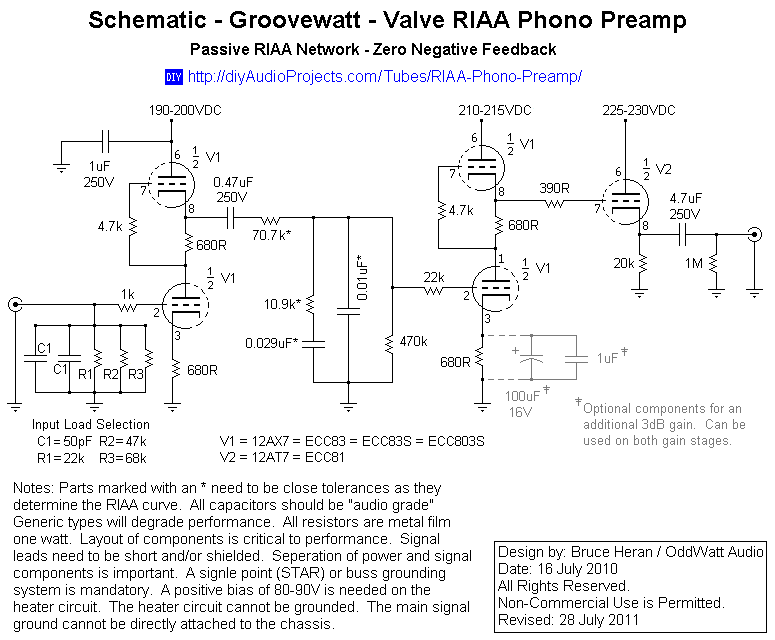
This project has been in development for over a year, initially postponed due to concerns about design complexity and the availability of high-quality phono preamps. The objective was to create a preamp that would deliver performance comparable to commercial...

The circuit utilizes three 3PDT toggle switches, a momentary soft-touch SPST footswitch, and a 4DPT footswitch. While these components are not rare, they are less commonly available than standard pedal parts. The design may be somewhat compact for larger...
This project is a successful vacuum tube amplifier utilizing a 6V6GT output pentode configured in triode mode, producing approximately 4.5 watts of output power. The design features a single-ended audio amplifier with a resistive input network, a driver stage,...
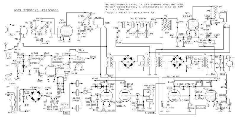
This true SSB transceiver is built around just 5 vacuum tubes, with no transistors nor ICs. Superhet receiver with AGC and S-meter drives a loudspeaker, 5W transmitter, very stable VXO uses CB crystals to cover 20m ham band. A...