
The MAX4108 4109 4308 4309 large capacitive load drive circuit diagram to enlarge
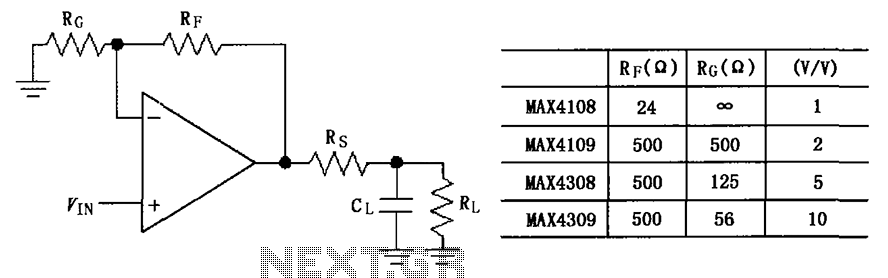
The MAX4108/4109/4308/4309 series of operational amplifiers are designed for high-speed applications, providing low distortion and high bandwidth. In scenarios where these amplifiers are tasked with driving capacitive loads, the inherent capacitance can interact negatively with the output stage of the amplifier, resulting in stability issues. The addition of an isolation resistor, Rs, serves a critical role in enhancing the stability of the circuit by dampening potential oscillations that arise from the interaction between the amplifier and the capacitive load.
The value of Rs, typically chosen between 15 to 20 ohms, is a compromise that balances the need to suppress overshoot without significantly affecting the output signal's integrity. A resistor value that is too high may introduce additional signal attenuation, while a value that is too low may fail to sufficiently dampen the overshoot and ringing. The choice of Rs should be validated through simulation or empirical testing to ensure optimal performance in the specific application context.
In practical applications, the layout of the circuit should also be considered to minimize parasitic inductance and capacitance, which can further exacerbate oscillation issues. Proper grounding techniques and short trace lengths between the amplifier output and the load can significantly improve stability. Additionally, the use of bypass capacitors near the power supply pins of the operational amplifiers can help maintain a stable voltage supply, further enhancing performance.
Overall, the implementation of an isolation resistor in conjunction with the MAX4108/4109/4308/4309 amplifiers is a well-established technique for ensuring reliable operation in environments where capacitive loads are present, thus maintaining signal integrity and system performance. As shown in FIG grounds MAX4108/4109/4308/4309 using the capacitive load driving circuit isolation resistor Rs constituted. MAX4108/4109/4308/4309 good AC characteristics, but it is not designed to drive high-load electrical resistance, its high reactive load will reduce its phase margin, causing a pulse signal overshoot ringing and ringing. The circuit between the output terminals and the load plus an isolation resistor Rs, for suppressing overshoot and ringing oscillations, Rs resistance is 15 ~ 20 .
Related Circuits
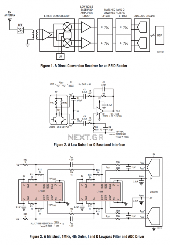
Figure 1 shows the block diagram of a direct conversion RF receiver—the receiver demodulates an RF carrier directly into a baseband signal without an intermediate frequency down-conversion (a zero IF receiver). The antenna, shared by both the transmitter and...
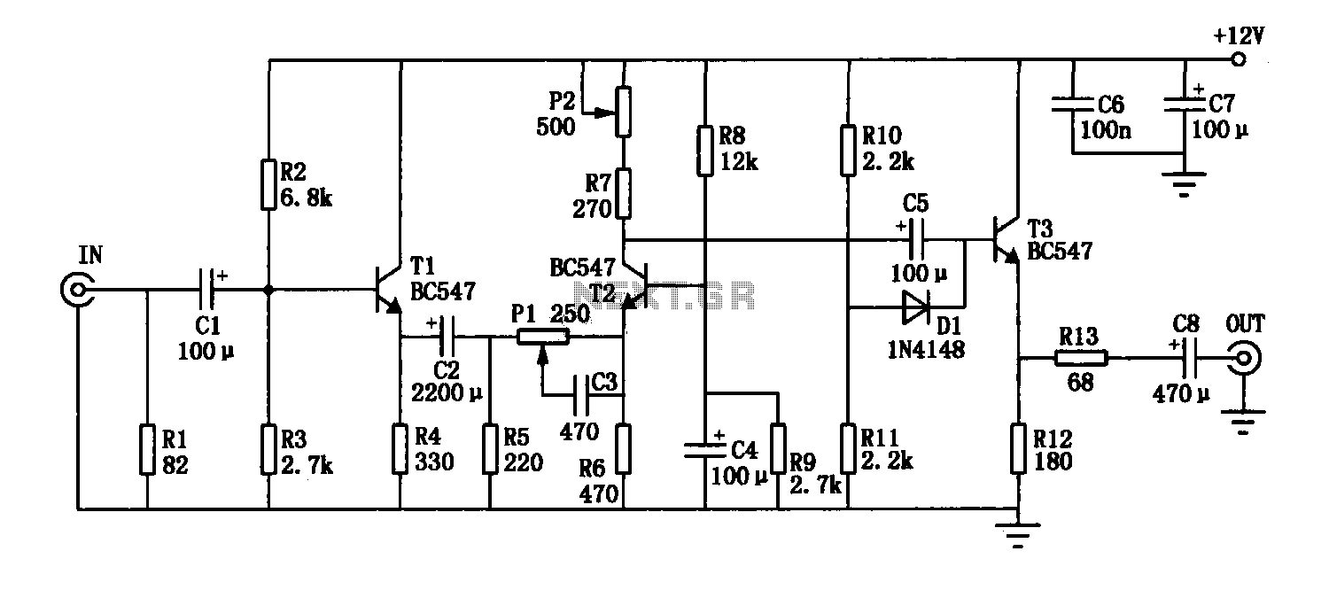
The enhancement circuit, as depicted, increases the high-frequency components of the video signal, thereby improving the contrast of the television image. It can be connected between the VCR and the TV SCART input. The circuit utilizes transistor T1 for...
This is a transistor inverter circuit diagram rated for 100 watts, designed as an easy-to-build circuit. It utilizes only transistors and does not incorporate any integrated circuits. The circuit converts a 12V battery input to a 220V, 50Hz square...
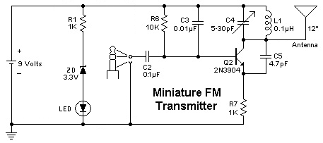
To replace a microphone with a 3.5" audio jack in a circuit, modifications will be necessary. The circuit currently utilizes an electret microphone, and adjustments must be made to accommodate the audio jack for audio transmission. The audio jack...
This project involves a light-activated alarm or morning alarm circuit that produces a pleasant melody upon detecting light. To use this circuit as a morning alarm, it should be placed in a location that receives morning sunlight. A 500K...
Short circuits or broken PCB tracks can be easily identified using a multimeter. However, this tool may yield inaccurate results when assessing the efficiency of a transistor or diode unless the device is unsoldered and removed from the PCB....
Warning: include(partials/cookie-banner.php): Failed to open stream: Permission denied in /var/www/html/nextgr/view-circuit.php on line 713
Warning: include(): Failed opening 'partials/cookie-banner.php' for inclusion (include_path='.:/usr/share/php') in /var/www/html/nextgr/view-circuit.php on line 713