
TDA1514 40 Watt Audio Amplifier Circuit
The described amplifier circuit is designed to provide a robust audio amplification solution suitable for various applications. The TDA1514 IC is favored for its reliability and performance, making it a preferred choice for audio enthusiasts. The circuit's simplicity allows for easy assembly, requiring only a minimal number of additional components, which contributes to its compact form factor.
The selection of a suitable transformer is crucial, as it directly affects the amplifier's performance. The transformer must be rated appropriately to handle the current requirements while providing sufficient voltage to the amplifier circuit. The use of large capacitors in the power supply helps to stabilize the voltage and improve transient response, essential for high-fidelity audio reproduction.
In terms of safety, the inclusion of fuses and proper grounding techniques is vital to prevent hazards associated with electrical faults. The loop breaker configuration is particularly effective in minimizing noise and interference, which can degrade audio quality.
Overall, this amplifier circuit exemplifies a balance between performance, simplicity, and safety, making it an excellent choice for those looking to build their own audio amplification system.This is a compact, easy to build amplifier that uses one IC only but delivers 40 watts of audio power. It is ideal for amplifying audio from your mobile CD player or iPod. The chip being used here is the TDA1514 originally brought to the market by Phillips/Valvo. The best characteristics of this chip is its high output power and robustness. It is available in a 9-pin SIL plastic package with a metal mount. Its package has a heat resistance of less than 1. 5K/W. This means that the heatsink must have a heat resistance of only 3. 8K/W when the chip reaches its maximum power dissipation of 19W (at Ub = +/-27. 5V, Tu = 500C). One can see from the diagram that only a handful of passive elements are needed to build the chip into a powerful audio amplifier. The power supply as supplied must be able to deliver a current of at least 3 amperes. The standby current consumption is about 60 mA. The supply voltage must never go beyond 27. 5 volts! In building the circuit, keep the wires to the power supply and outputs as short as possible. The resistos R4 and R5 set the voltage gain at the feedback which, in this case, is between 20 and 46 dB.
For a single channel amplifier(mono), a 80 VA transformer (T1) should be sufficient. If you construct two channels (or stereo) amps, 120 VA is recommended. Capacitors Cx and Cy should be at least 4. 700uF rated at 35V. It can be up to 10. 000uF. Capacitors twice as large discharge slower giving better peak power potential resulting to better power output. Feel free to increase the capacitance but take note that you may not get much additional benefit for the price involved.
Make sure they are connected the right way around too or they will blow and cause injury. A 0. 25 mA fuse (F1) should be installed. If using toroidal transformer, the fuse must be a time delay (slow blow) variant. Be sure to correctly earth the supply and any metal casing around it. The components on the earth and ground connections (Dx, Dy, Rx, Cz) form a loop breaker. This is recommended because it can eliminate those troublesome earth loops. Rx is a 5 W or better wirewound resistor. The Cz capacitor must be rated for 250 V AC. Do NOT use a 250 V DC capacitor for Cz as it would fail if there ever was a fault causing mains current to flow to earth. Dx and Dy are rated at 250 V/ 1 A. If your local rules and regulations prohibit constructing this, omit all these components and connect the earth to ground but NEVER disconnect the earth lead it could save your life or somebody elses!
Constructing the power supply for this amplifier is simple. As shown on the schematic above you need to wire up a 18-0-18 (center tapped) transformer in order to get the recommended +/- 25V. Be very careful since this construction involves mains wiring. 🔗 External reference
Related Circuits
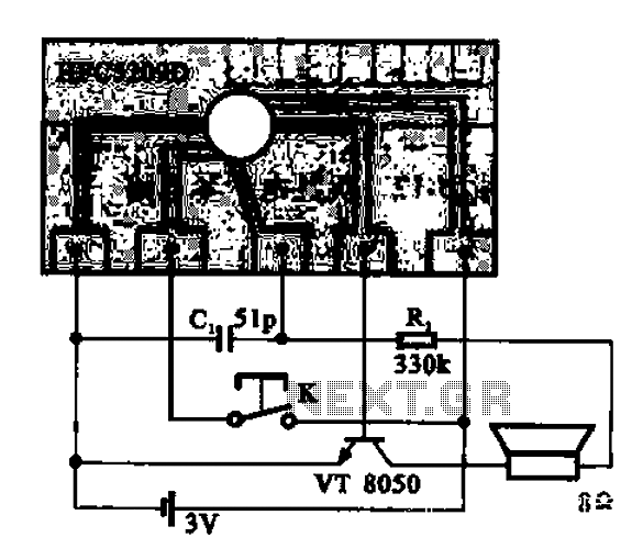
A simple phone automatically displays the recording circuit. In this circuit, after the call, the Ming sound start switch K is activated by the sound of the automatic message HFC5209D. The described circuit functions as an automatic call recording system...
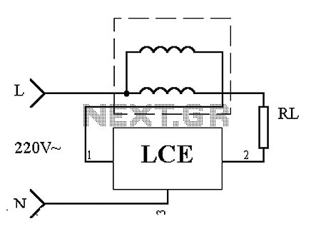
This is an application circuit of the device as illustrated in principle. In the meter, the voltage and current coils are connected to the power line, regardless of whether a load is connected. The voltage coil consistently draws power,...
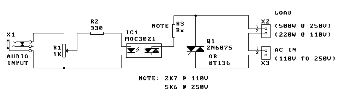
A music-to-light modulator is a circuit which controls the intensity of one or more lights in response to an audio input. The problem in older circuits is that there was a direct electrical connection between the lights using mains...
This microphone preamplifier utilizes the low-noise integrated circuit uA739. The circuit serves as an example of an effective preamplifier design for dynamic microphones. The integrated circuit contains two identical preamplifier circuits, with the second preamp functioning in the same...
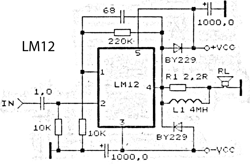
This is an amplifier circuit utilizing the LM12 integrated circuit as the primary amplifier. The amplifier delivers a power output of 150 watts and operates with a load impedance of 4 ohms. It is classified as a high-output power...
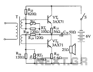
The following diagram illustrates a common output transformerless (OTL) amplifier circuit that delivers an output power of 100 mW. The circuit includes an output transformer and a capacitor, which work in conjunction with speaker units. The frequency characteristics of...