
basic circuit diagram design

The circuit involves interfacing four mechanical switches with a USB joystick interface. The USB joystick board typically operates at a voltage of +5V, which is standard for USB-powered devices. Each switch will be connected to a digital input pin on the joystick board.
To achieve this, the following steps should be taken:
1. **Power Supply**: Connect the +5V output from the USB joystick board to one terminal of each switch. The ground connection from the USB board should be connected to the common ground of the circuit.
2. **Switch Connections**: The other terminal of each switch should be connected to a separate digital input pin on the joystick board. When a switch is pressed, it will complete the circuit, allowing current to flow from the +5V through the switch to the input pin, simulating a button press.
3. **Pull-Down Resistors**: To ensure that the input pins read a stable LOW state when the switches are not pressed, pull-down resistors (typically 10kΩ) should be connected from each input pin to ground. This configuration prevents floating inputs, which can lead to erratic behavior.
4. **Debouncing**: Mechanical switches can produce noise when pressed or released, leading to multiple signals being registered. To mitigate this, a debouncing circuit can be implemented either in hardware using an RC filter or in software by programming the joystick board to ignore rapid state changes.
5. **Testing**: Once the connections are made, the circuit should be tested by pressing each switch and observing the corresponding output on the joystick board. This can be done using a computer or a microcontroller that can read USB joystick inputs.
This setup allows for a straightforward and effective way to utilize mechanical switches as input devices for various applications, enhancing user interaction with USB-compatible systems.Hi! I have a 4 switches that I`m goin to connect to a USB joystick board. The USB board has +5V and ground connections, and emulate a button press on.. 🔗 External reference
Related Circuits
This is a simple 1.5V powered LED flasher circuit diagram. This circuit can flash 1.7V or 2.3V LEDs (depending on the color) using a 1.5V DC input. The LED will turn on when the 100µF capacitor is charged by...

The OCL power amplifier circuit is an integrated circuit. Circuit IC1 is an integrated circuit, and its internal circuit configuration is substantially similar to the OTL power amplifier circuits. The OCL (Output Capacitor-Less) power amplifier circuit is designed to provide...

This is a simple FM transmitter circuit schematic diagram that utilizes a single transistor, S9014. The FM transmitter circuit operates by modulating an audio signal onto a carrier frequency, which is typically in the FM band. The S9014 transistor serves...
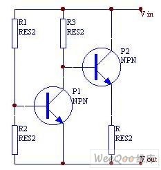
When the current is below the specified threshold, the bias current supplied by resistor R1 causes transistor P3 to saturate and conduct. In this state, it is unable to regulate the current effectively. Conversely, when the current reaches or...
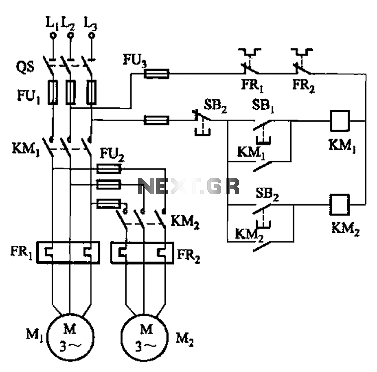
The circuit illustrated in Figure 3-83 demonstrates that the contactor KMi is activated only after it is pulled, which indicates that the motor Mi has started for the first time. Following this, the contactor KM2 is then activated, indicating...

An NE592 or LM733 is utilized as a general-purpose video amplifier in this schematic. J2 and J3 deliver two anti-phase outputs. R2 functions as a gain control. The bandwidth is approximately 100 MHz. The NE592 and LM733 are operational amplifiers...