
Electronic Selector for 10 sources with Display-Relay Drive circuit
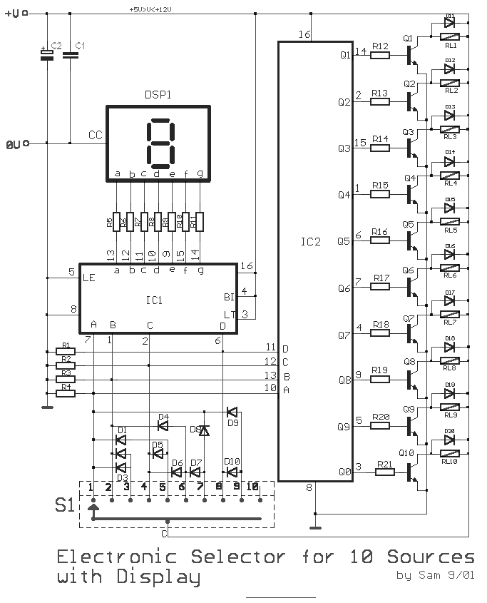
The circuit operates by allowing the user to select between multiple power sources or signal inputs through a mechanical rotating switch (S1). This switch is connected to a series of relays (RL1 to RL10), which are electronically driven to switch the selected source to the output. Each relay corresponds to a specific input or source, enabling the circuit to handle various operational requirements.
The electronic drive for the relays is typically implemented using a microcontroller or a dedicated relay driver IC, which receives input from the rotating switch. This design ensures that the selected relay is activated while others remain deactivated, preventing cross-talk between sources. The relays are chosen based on their switching capacity to handle the required voltage and current levels of the signals being managed.
To provide visual feedback to the user, an optical indication is achieved through the display (DSP1). This display can be an LED array, LCD, or other types of visual indicators that illuminate or change state to reflect the current selection made via the switch. The display is updated in real-time as the switch is rotated, ensuring the user is always aware of which source is currently active.
The overall design emphasizes reliability and user-friendliness, making it suitable for applications where multiple sources need to be managed efficiently, such as in audio systems, power distribution systems, or laboratory setups. Proper consideration should be given to the layout of the circuit to minimize noise and interference, particularly in sensitive applications. Additionally, the selection mechanism should be robust to ensure longevity and consistent performance over time.This is a circuit for alternative sources selection. It combines mechanical selection using a rotating switch S1, the electronic drive of the relays RL 1-10 and also the optical indication of the selection by the Display DSP1.. 🔗 External reference
Related Circuits
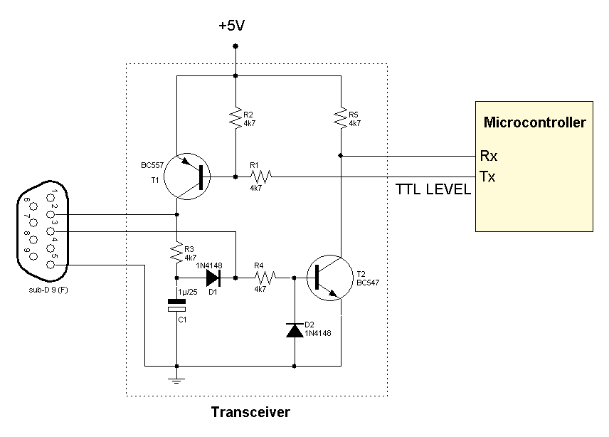
Several RS232 transceiver circuits are used for communication between microcontrollers and other devices, such as PCs or RS232 devices. This document presents a collection of well-known RS232 transceiver circuits. The circuit utilizes the MAX232 from Maxim's devices, which is...

This circuit is a fourth-order low-pass filter designed for operation at kilohertz frequencies. The component values for resistors R1, R2, and capacitors C1, C2, as well as resistors R3, R4 and capacitors C3, C4 can be adjusted for functionality...

Detecting electrical equipment sometimes requires disconnecting the circuit in series for more accurate measurements of electrical current using an ammeter. However, restoring the circuit to its original state is necessary, as it can affect the normal operation of electrical...
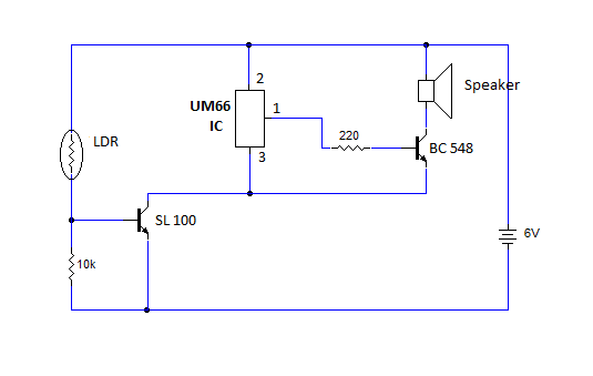
This article provides instructions for creating a light-sensitive morning alarm circuit. The circuit utilizes an LDR (Light Dependent Resistor) or photoresistor to detect morning light, which triggers the alarm section. When light is detected, the circuit produces a melodious...
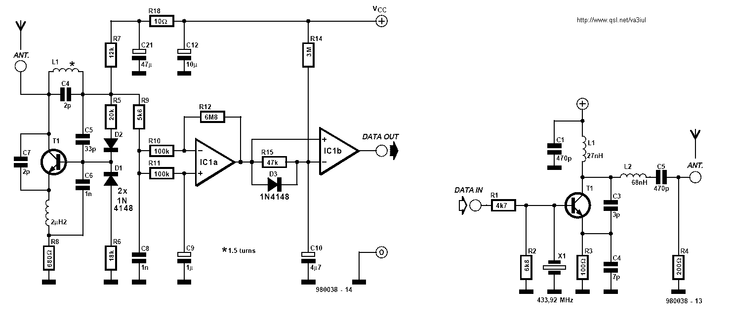
The purpose of this circuit is for research and education. Assistance is sought in acquiring components for simple RF circuits, as well as tutorials or schematics. The requester is facing challenges in locating quality resources for beginner-level RF circuit...
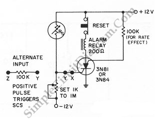
When the resistance value of temperature, light, pressure, or any other resistive sensors (Rs) drops below a certain threshold, which can be adjusted by a preset. In electronic circuits, resistive sensors such as thermistors, photoresistors, and piezoresistors are commonly used...