
4040B LED Counter
In this circuit, a counter is utilized to count the number of input pulses. The output of the counter is connected to a light-emitting diode (LED), which serves as a visual indicator of the pulse count. When pulses are received at the input, the counter increments its count, and each increment can be represented by the LED's illumination.
To design this circuit, the following components are typically used:
1. **Counter IC**: A digital counter IC, such as the 4017 decade counter or a binary counter like the 74HC393, is employed to count the incoming pulses. The counter IC will be powered by a suitable voltage supply, typically between 3V to 15V, depending on the specific IC used.
2. **Input Signal**: The input signal can be generated from various sources, such as a switch, a sensor, or a waveform generator. The input pulses should be within the operational frequency range of the counter IC.
3. **LED**: The LED is connected to one of the output pins of the counter. A current-limiting resistor is also required in series with the LED to prevent excessive current from flowing through it, which could damage the LED. The resistor value can be calculated based on the supply voltage and the forward voltage drop of the LED.
4. **Power Supply**: A stable power supply is essential for the reliable operation of the circuit. The voltage should match the requirements of both the counter IC and the LED.
In operation, as the input pulses are received, the counter increments its output. The LED will light up each time the counter reaches a specific output state, providing a clear visual indication of the pulse count. This setup is particularly useful in applications where monitoring pulse counts visually is necessary, such as in educational demonstrations or simple counting applications.
Overall, this circuit effectively combines digital counting with a visual output, facilitating easy monitoring of pulse activity.The number of the pulses of the input can be confirmed by seeing it with the eyes by putting the light-emitting diode to the output of the counter .. 🔗 External reference
Related Circuits
If you have ever attempted to dim an LED using a simple potentiometer, it is recognized that this method is not very effective. Similar to standard diodes, the voltage-current characteristic of LEDs is non-linear. Consequently, depending on the potentiometer...
This is an image Schematic. No Description available. The provided input indicates that there is an image schematic without any accompanying descriptive details. In the absence of specific schematics or circuit details, it is essential to consider the typical...
After receiving a Micro Scalextric set for Christmas and acquiring a large quantity of second-hand track from eBay, a lap counter was deemed necessary for racing against the clock and opponents. The objective was to accurately time laps, rather...
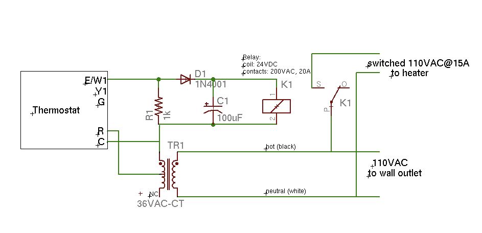
A basic schematic of the circuit is presented, marking the initial experience with Eagle software. It is important to note that only the W1 output of the thermostat is utilized, while C serves as the common connection. The schematic outlines...
Twelve LEDs can be arranged in a circle to represent the twelve hours of a clock face, while an additional twelve LEDs can be arranged in an outer circle to indicate five-minute intervals within the hour. Four additional LEDs...
A battery-status indicator circuit is useful for monitoring portable test equipment and similar devices. LED D1 flashes to attract the user's attention, signaling that the circuit is operational, preventing it from being left on unintentionally. The circuit produces approximately...