
Space heater controlled by digital thermostat Schematic
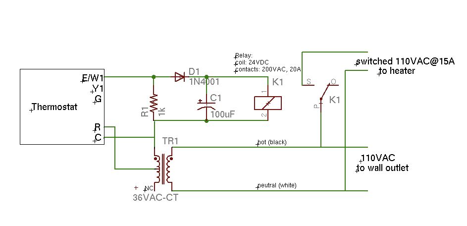
The schematic outlines a simple circuit design where the thermostat's W1 output is connected to a load, such as a heating element or fan, facilitating temperature control in a system. The common terminal, labeled as C, provides a reference point for the circuit, ensuring proper operation of the thermostat.
In a typical configuration, the W1 output activates when the temperature falls below a predetermined threshold, allowing current to flow to the connected load. This action is essential for maintaining the desired environmental conditions. The common terminal (C) is typically connected to the power supply's negative or ground, establishing a complete circuit for the thermostat to function effectively.
For enhanced reliability, it is advisable to include protective components such as a fuse or circuit breaker in the design to prevent overcurrent situations that could potentially damage the thermostat or the load. Additionally, utilizing a relay can provide isolation between the thermostat and the load, allowing the circuit to handle higher power levels while ensuring the thermostat operates within its rated specifications.
Overall, this schematic serves as a foundational representation for a temperature control system, illustrating the essential components and their interconnections. Further refinements may include incorporating additional features such as indicators or more complex control logic, depending on the specific application requirements.Here is a rough schematic of the circuit (also my first experience with Eagle!). Notes: Only the W1 output of the thermostat is used. C is the common.. 🔗 External reference
Related Circuits
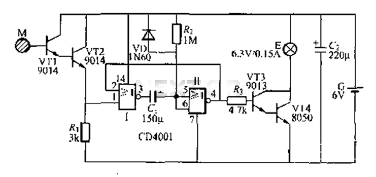
A two-battery powered light touch delay circuit designed for convenience at night. It can be placed on a bed pillow, and when the metal contact M under the capsule is touched, a small lamp will automatically light up. The...
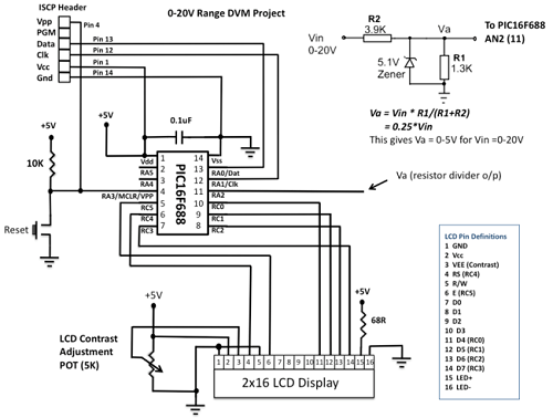
This project details the construction of a digital voltmeter utilizing a PIC microcontroller. A character-based HD44780 LCD display is employed to visualize voltage measurements. The microcontroller selected for this project is the PIC16F688, which features 12 I/O pins, with...
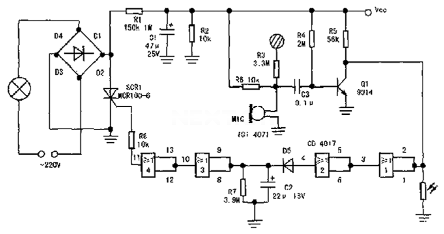
The circuit diagram illustrates a sound, light, and touch-controlled delay self-extinguishing switch. It comprises three main sections: the power circuit, the signal conversion detecting circuit, a delay circuit, and a control circuit. 1. Power Circuit: This section consists of...
Cellphone Operated Land Rover (Mobile Phone Operated Robot). In this project, the robot is controlled by a mobile phone that makes a call to the mobile phone attached to the robot. The cellphone operated Land Rover project involves the design...
The copyright of this circuit is owned by Smart Kit Electronics. This document discusses improvements and modifications based on the original schematic. It describes a straightforward yet highly accurate and useful digital voltmeter designed as a panel meter, suitable...
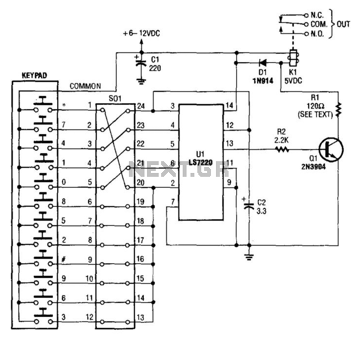
A keypad is used to input a four-digit access code, which is configured using jumpers on a 24-pin plug-in header and socket. The component Ul is an LST220, which detects a sequential four-digit data input. Upon successful entry of...