
Easy Alarms Police / Ambulance Electronic

This electronic schematic represents a basic alarm system intended for use in police and ambulance applications. The design is optimized for straightforward assembly, making it accessible for both novice and experienced builders. The circuit typically consists of a sound-generating component, such as a buzzer or speaker, and a triggering mechanism, which may include push buttons, motion sensors, or other activation devices.
The primary components of the circuit include a microcontroller or a simple transistor-based configuration that controls the sound output. The circuit can be powered by a standard DC power supply or batteries, ensuring portability and ease of installation in various environments.
The simplicity of the circuit allows for easy modifications, such as adjusting the sound frequency or integrating additional features, such as LED indicators that activate alongside the alarm. The cost-effective nature of the design makes it suitable for implementation in various applications, from personal safety devices to larger public safety systems.
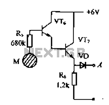
In summary, this police and ambulance alarm circuit provides an efficient solution for alerting individuals to emergencies, combining straightforward construction with affordability and adaptability.The following circuit shows about Alarms Police / Ambulance electronic Diagram Design. Features: simple and easy to assemble, Cheap circuit, .. 🔗 External reference
Related Circuits

This design was created at the request of an individual to operate a 240V AC heater in an orchid box, maintaining a higher temperature during daylight hours than at night. A simple regulator is employed to achieve a stabilized...
Delay electronic doorbell circuit - touch doorbell amplifier circuit The delay electronic doorbell circuit is designed to provide a user-friendly interface for doorbell activation, utilizing a touch-sensitive amplifier circuit. This circuit typically incorporates a touch sensor that detects user interaction,...

When the doorbell switch is pressed, two monostable stages are sequentially activated, applying bias to a pair of voltage-controlled resistor stages. These stages modulate the outputs from a pair of tone generators. The resulting signals are then fed to...
The 555 timer on the right is configured as an alarm sound generator, while the second 555 timer on the left operates as a 1 Hz astable multivibrator. The output from the left timer modulates the frequency of the...

A video and the circuit with schematics for connecting and controlling the world's smallest linear actuator based on a bipolar stepper motor from a Blu-ray drive. The project involves the design and implementation of a circuit to control a linear...

This door minder electronic project is based on a 555 timer circuit and utilizes an infrared (IR) beam to monitor doorways, passageways, or any other designated area. When the IR beam is interrupted, a relay is activated, which can...