
4093 Cmos Vfo Circuit
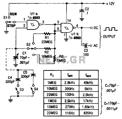
The described circuit employs two NAND gates from a Quad 4093 integrated circuit, configured to function as an astable multivibrator. This configuration generates a continuous square wave output, making it suitable for applications such as clock pulses or tone generation. The astable multivibrator operates without a stable state, continuously oscillating between its high and low states.
The variable capacitor, CI, which consists of three parallel sections rated at 365 pF, allows for fine-tuning of the oscillation frequency. By adjusting the capacitance value, the duty cycle and frequency of the output waveform can be modified, providing flexibility in circuit performance.
Switches S3 and S4 are incorporated into the design to enable the addition of external capacitors, which can further modify the timing characteristics of the multivibrator. This feature allows for a broader range of oscillation frequencies, enhancing the versatility of the circuit for different applications. The use of external capacitors can also help in achieving desired frequency stability or specific timing intervals as required by the application.
In conclusion, the astable multivibrator circuit featuring the Quad 4093 and the variable capacitor arrangement, supplemented by optional capacitors through switches, provides a robust solution for generating square wave signals with adjustable frequency and duty cycle. Two gates of a Quad 4093 are used in an astable multivibrator. CI is a three-gang 365 pF variable capacitor with sections paralleled. S3 and S4 switch in optional extra capacitors. 🔗 External reference
Related Circuits
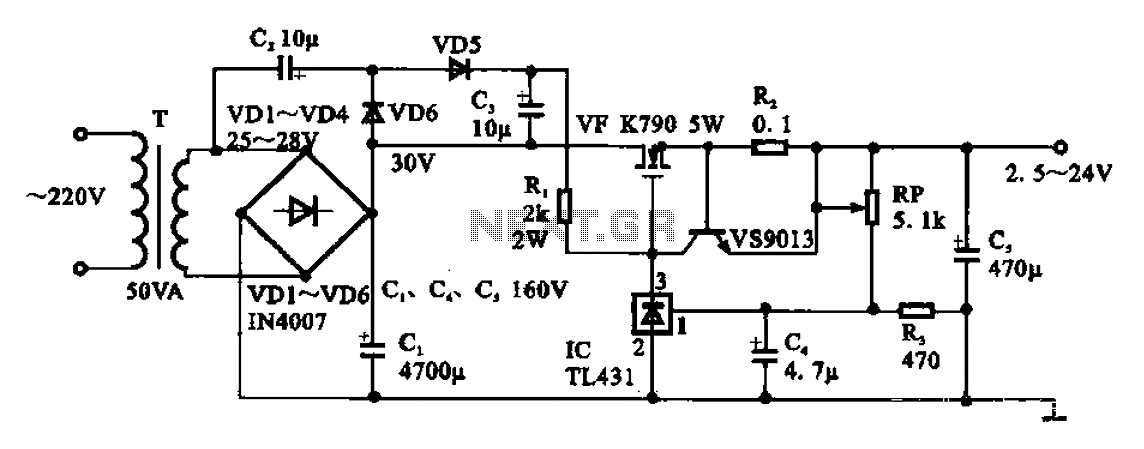
An adjustable DC power supply circuit is presented, consisting of a step-down transformer (T), a rectifier bridge (VD1 to VD4), and additional components. The voltage regulator circuit includes an adjustment potentiometer (RP, 5.1 kΩ), allowing the output voltage to...
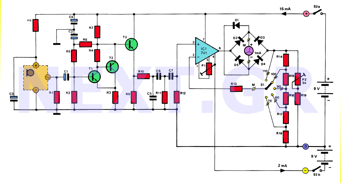
The human ear can detect sounds ranging from 20Hz to 20KHz, with the normal range typically between 100Hz and 13KHz, depending on an individual's age and health. For accurate measurements, a range of 20Hz to 20KHz is used. Sounds...
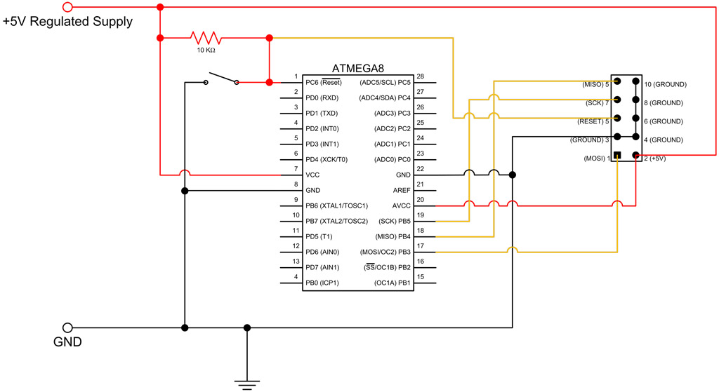
This tutorial continues from the ATmega8 Breadboard Circuit Part 1, where a small power supply was built on a breadboard. In this part, the ATmega8 microcontroller will be added along with an interface for programming. The first step is...
The transmitter provides an optical link (infrared) for headphones. Three infrared LEDs (IR) are powered by T1, with P1 used to adjust the current level. The current consumption of this headphones infrared transmitter is approximately 60mA at 9V. The infrared...
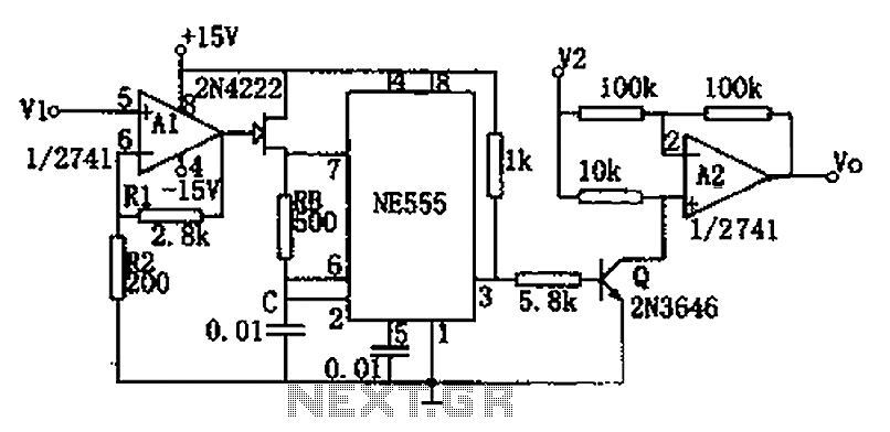
The circuit depicted in the figure consists of a voltage-frequency converter and an amplitude modulator. The input voltage V1, processed by operational amplifier A1, controls the FET 2N4222's internal resistance, which in turn alters the oscillation frequency of the...

This is a design circuit for a low-cost FM antenna booster that can be used to listen to programs from distant FM stations clearly. The antenna FM booster circuit comprises a common-emitter tuned RF preamplifier wired around the VHF/UHF...
Warning: include(partials/cookie-banner.php): Failed to open stream: Permission denied in /var/www/html/nextgr/view-circuit.php on line 713
Warning: include(): Failed opening 'partials/cookie-banner.php' for inclusion (include_path='.:/usr/share/php') in /var/www/html/nextgr/view-circuit.php on line 713