
Adjustable DC power supply circuit
The adjustable DC power supply circuit is designed to provide a stable output voltage that can be tailored to meet specific requirements. The circuit begins with a step-down transformer, which reduces the input AC voltage to a lower AC voltage suitable for rectification. The transformer is selected based on the desired output voltage and current specifications.
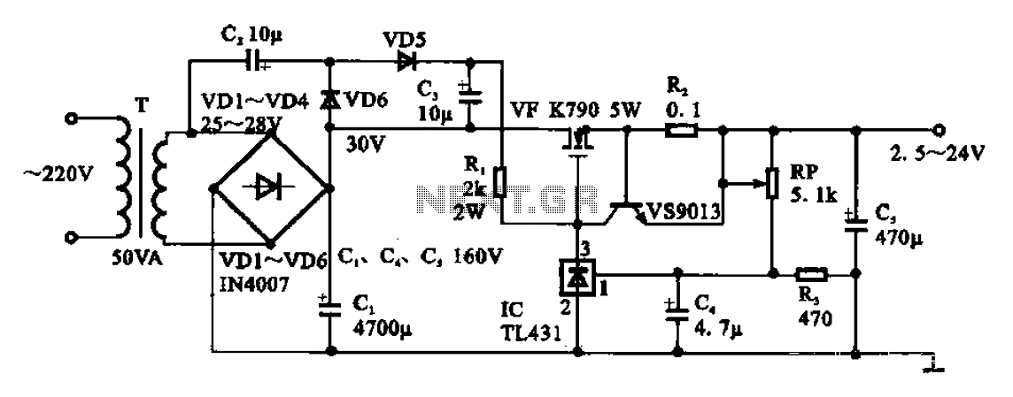
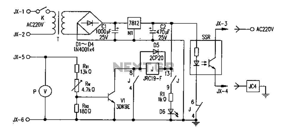
Following the transformer, a rectifier bridge composed of four diodes (VD1 to VD4) converts the AC voltage to pulsating DC. The rectifier bridge is configured in a full-wave arrangement, ensuring efficient conversion and minimizing ripple voltage. The output from the rectifier is then smoothed using a capacitor to reduce voltage fluctuations, providing a more stable DC voltage.
The heart of the circuit is the voltage regulator, which maintains the output voltage at the desired level despite variations in input voltage or load current. The adjustment potentiometer (RP, 5.1 kΩ) is connected to the voltage regulator, allowing users to fine-tune the output voltage within a range of 2.5 V to 24 V. This feature is particularly useful for applications requiring different voltage levels, such as powering various electronic devices or experimental setups.
For optimal performance, careful consideration should be given to the selection of components, including the transformer rating, diode specifications, and capacitor values. Additionally, heat dissipation must be addressed, particularly in the voltage regulator, to prevent thermal shutdown or damage.
Overall, this adjustable DC power supply circuit is a versatile solution for providing variable DC voltages, suitable for a wide range of electronic applications.Adjustable DC power supply circuit Shows an adjustable DC power supply circuit, which is composed of step-down transformer T, rectifier bridge pile (VD1 ~ VD4) and other parts of the voltage regulator circuit, the adjustment potentiometer RP (5.i kfl), the output voltage varies between 2.5-24 V.
Related Circuits
The circuit is an amplifier with bias at cutoff. Transistor Q5 functions similarly to a grid-leak detector. In the absence of a subcarrier input, the demodulator is disabled, preventing any signals from passing through. It is essential for the...

Currently, a high-quality communications receiver utilizes diode ring mixers and a double differential pair balanced modulator, configured as an analog multiplier (MC1496). The mixer circuits are illustrated in the accompanying figure. The local oscillator (LO) voltage and the input...
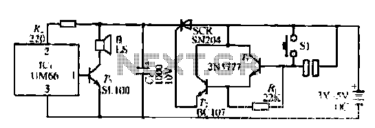
A few custom integrated circuits began to play music. When the song ends, no electricity flows through the thyristor, which then cuts off the light, causing the phototransistor to activate. The system is designed with a touchpad; each touch...
PC parallel port can be very useful I/O channel for connecting your own circuits to PC. The PC's parallel port can be used to perform some very amusing hardware interfacing experiments. The port is very easy to use when...
The FM302E-I-type FM transmitter exciter is utilized in Japan's NEC HPB a 1210 motherboard. It features direct carrier frequency modulation, phase-locked frequency stabilization, and frequency synthesis. The preamplifier (BLF-177 FET) is directly driven by an actuator, achieving a maximum...
This is a very simple project using a printed circuit board and 8 components. It will flash an ordinary 3mm or 5mm (1/8" or 1/4") LED at a rate of about one flash per second. This circuit works on...
Warning: include(partials/cookie-banner.php): Failed to open stream: Permission denied in /var/www/html/nextgr/view-circuit.php on line 713
Warning: include(): Failed opening 'partials/cookie-banner.php' for inclusion (include_path='.:/usr/share/php') in /var/www/html/nextgr/view-circuit.php on line 713