
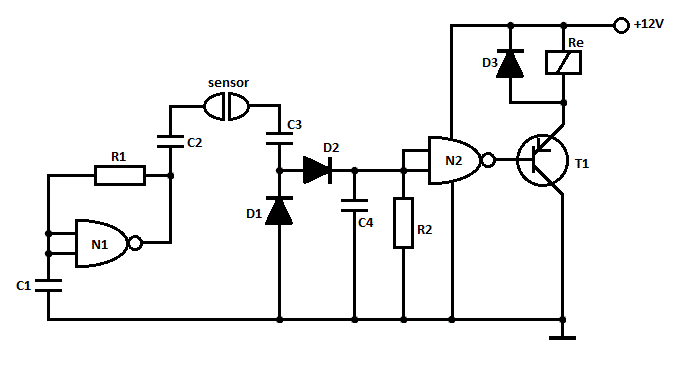
40KHz LASER BURST DETECTOR

The circuit operates by utilizing a photodetector, such as a photodiode or phototransistor, which is sensitive to the specific wavelength of the laser light. The incoming laser light is focused onto the photodetector, allowing it to convert the light signal into a corresponding electrical signal. The sensitivity of the circuit is crucial, as it must detect low-intensity laser bursts that may be reflected off the projection screen.
Upon detection of a laser pulse, the photodetector generates a voltage change that is processed by a comparator or an operational amplifier configured as a threshold detector. This component is set to trigger when the voltage exceeds a certain level, indicating the presence of the laser burst. The output from the comparator is then fed into a monostable multivibrator, which is configured to produce a 100 ms output pulse. The duration of this pulse can be adjusted by changing the timing components (resistors and capacitors) associated with the multivibrator.
The circuit's design includes a bandpass filter to isolate the 40 kHz modulation frequency of the laser signal, ensuring that only the relevant signals are processed. This filter helps to minimize false triggers from ambient light or other noise sources. Additionally, the circuit can be equipped with adjustable gain settings to enhance sensitivity for different applications, including long-range laser communications.
For applications beyond firearm training, modifications can be made to increase the range and sensitivity, such as using higher-gain photodetectors or optimizing the optical components to focus more light onto the sensor. The versatility of this circuit allows it to be adapted for various laser detection applications, making it a valuable component in both training and communication systems.This circuit was originally designed to detect weak flashed of laser light bounced off of a fabric video projection screen. It was used as part of a firearm training system. It generates a 100mS output pulse whenever it detects a 3ms to 5ms-laser burst, modulated at 40KHz. It is very sensitive and could be modified for long-range laser communications 🔗 External reference
Related Circuits
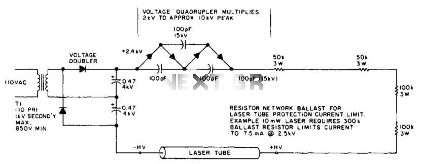
This circuit delivers a peak voltage of 10 kV, while limiting the current to 7.5 mA at 2 kV. The resistors included in the design serve the purpose of ballasting. Additionally, the starting circuit is unable to sustain the...
This project is inspired by the DPRG IRPROX project, which features an excellent PCB layout and concept. Appreciation is extended to them for sharing their project, which has significantly accelerated the learning process in PIC programming. The board's pinout...
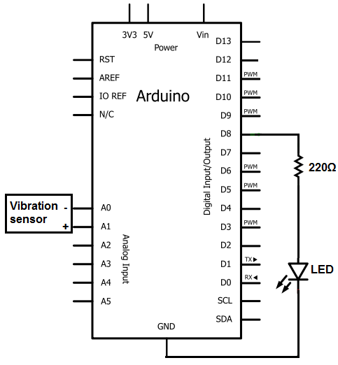
The sensors consist of a thin strip of piezoelectric material with a rivet at one end acting as a weight. When vibration occurs, the weight moves, stressing the piezo material, which generates a spike in voltage that can reach...
Thanks to the S6986, the circuit is very simple and requires few components. D2, D3, D5 and D6 forms a bridge rectifier allowing to plug the sensor connector brick in any direction. C1 filters power supply, it must be...
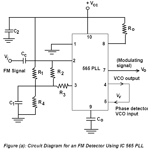
Phase Lock Loop (PLL) FM Detector with 565 PLL IC. The circuit diagram and internal structure of the PLL IC 565 are shown in the given figures. The Phase Lock Loop (PLL) FM Detector utilizing the 565 PLL IC is...
This is a straightforward liquid detector that utilizes a relay to activate an evacuation mechanism. It can be employed for water or any liquid that conducts electricity. Any PNP transistor capable of handling the relay current can be used....