
40M Cw Transmitter Circuit
The CW transmitter circuit is designed for efficient operation, providing flexibility in output power levels based on the supply voltage applied. The choice of a low-Q inductor L1 is critical, as it influences the bandwidth and stability of the transmitter. A low-Q inductor minimizes losses and allows for a broader frequency response, which is essential for maintaining signal integrity in communication applications.
Transistor Q1 must be carefully selected to handle the specified voltage levels, ensuring that it operates within safe limits to prevent damage. The design includes a voltage divider configuration that utilizes capacitor C3 and resistor R2 to establish the required 12-volt reference point at the junction, thereby protecting Q1 from excessive voltage.
The removal of inductor L5 is a crucial step in modifying the circuit configuration, as it may impact the overall performance and tuning of the transmitter. By adjusting the values of R6, the designer can fine-tune the quality factor of the circuit to achieve the desired balance between efficiency and output stability. The maximum resistance of 47 ohms provides a practical range for achieving the necessary Q reduction without compromising the transmitter's operational capabilities.
Overall, this CW transmitter circuit offers a robust solution for generating continuous wave signals, with careful consideration given to component selection and configuration to optimize performance and reliability. This CW transmitter has an output of up to 3 W. By using 24 V on Q2, up to 10 W output can be obtained. If a 24-V supply is used, Ql must not see more than 12 V. Connect 12 V between junctions C3, R2 and L2, and remove L5. LI should be a low-Q 18- to 20- inductor. R6 can be used (up to 47 ) to reduce the Q further. 🔗 External reference
Related Circuits
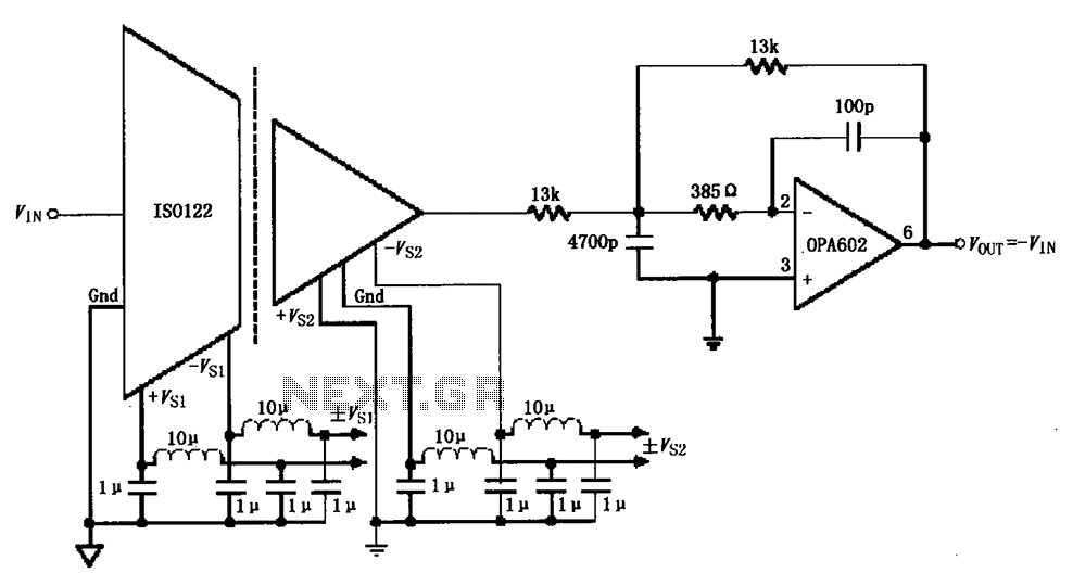
The ISO122/124-type filter circuit is designed to address noise suppression from the DC/DC converter. The internal oscillator frequency of the ISO122/124 modem is set to 500 kHz. The circuit employs inductors and capacitors for filtering to mitigate any beat...
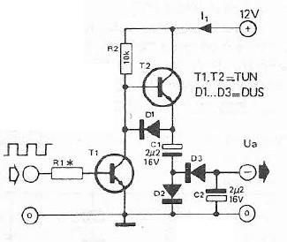
Voltage inverter circuit design electronic project using few electronic components The voltage inverter circuit is a fundamental electronic project that converts direct current (DC) to alternating current (AC). This circuit is particularly useful in applications where AC voltage is required...
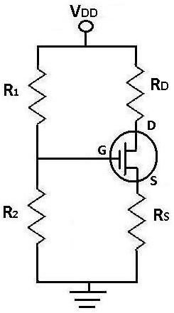
During DC analysis, all AC voltage sources are removed from the circuit since they are AC sources. DC analysis focuses solely on DC sources. Additionally, all capacitors are removed because, in a DC context, capacitors act as open circuits....
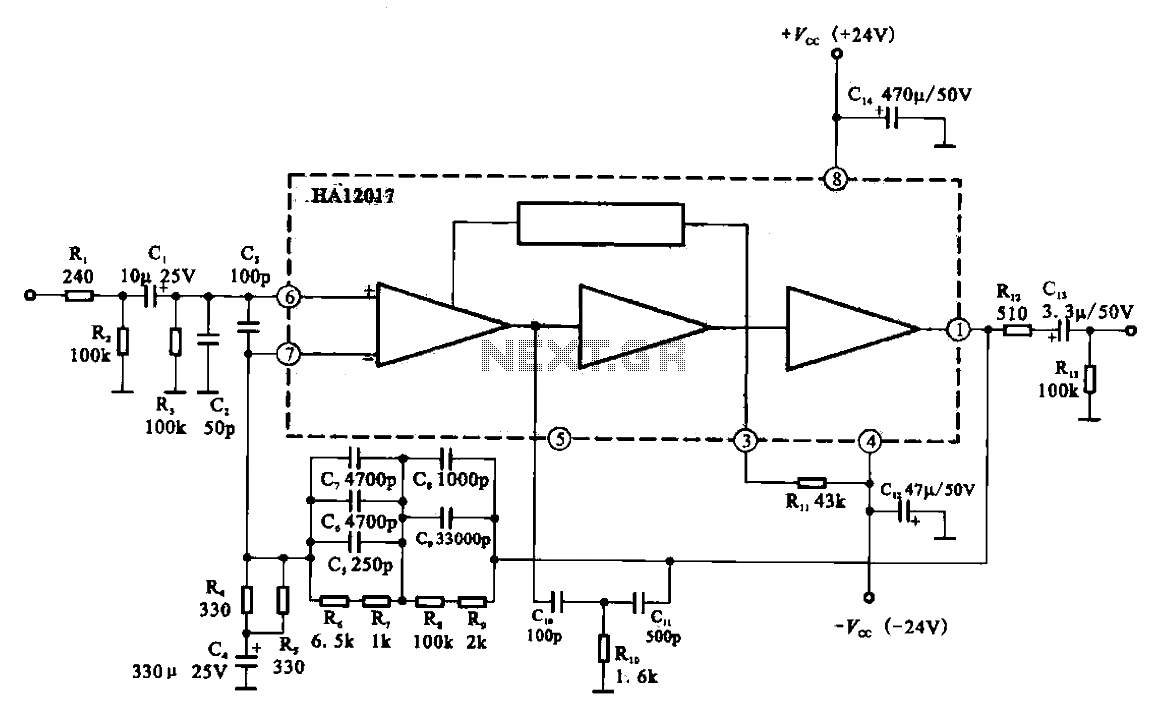
Low-noise preamplifier circuit. This circuit demonstrates a typical low-noise preamplifier design, which can be utilized to amplify signals from sources such as magnetic heads and microphones within audio applications. The input signal is coupled through a capacitor and subsequently...
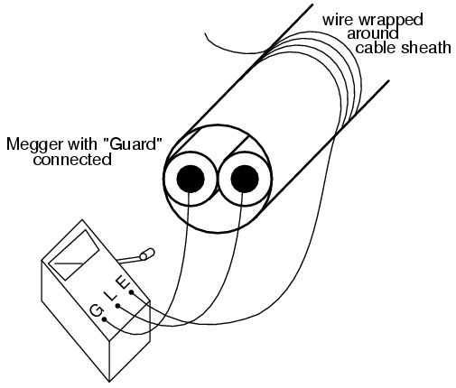
A meter is a device designed to accurately detect and display an electrical quantity in a form that is readable by humans. This "readable form" is typically visual, such as the motion of a pointer on a scale, a...
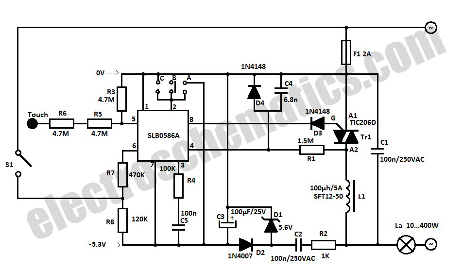
The SLB0586A integrated circuit from Siemens can be utilized to create a simple touch light dimmer circuit, allowing for the adjustment of lamp intensity. When paired with a TIC206D triac, this setup enables smooth regulation of light intensity for...