
DC Analysis of a MOSFET Transistor Circuit
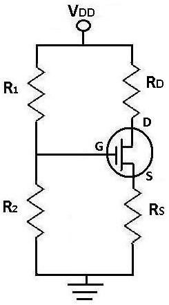
In the context of DC analysis for a MOSFET circuit, the process begins by simplifying the circuit to focus only on the relevant DC components. This involves removing all AC sources and capacitors, which simplifies the analysis significantly. The MOSFET's gate-source voltage, Vgs, is critical as it directly influences the operation of the transistor. Vgs must be calculated accurately, as it determines whether the MOSFET is in the cutoff, triode, or saturation region.
To calculate Ids, the drain-source current, it is necessary to apply the MOSFET equations, which typically involve quadratic relationships. The standard equation for Ids in saturation is given by:
\[ Ids = \frac{1}{2} k_n (Vgs - Vtn)^2 \]
where \( k_n \) is the transconductance parameter and \( Vtn \) is the threshold voltage.
After substituting the calculated Vgs into this equation, the resulting quadratic equation will yield two possible values for Ids. The critical step is identifying the correct current that corresponds to a Vgs greater than Vtn. The other solution, which does not meet this criterion, indicates an invalid operating point for the circuit and should be discarded. This method ensures that the analysis yields a valid and functional current value that can be used for further circuit design and optimization.
In summary, the DC analysis process is integral for understanding the behavior of MOSFETs in circuits, as it allows for the determination of critical parameters that dictate the performance of the device under DC operating conditions.When doing DC analysis, all AC voltage sources are taken out of the circuit because they`re AC sources. DC analysis is concerned only with DC sources. We also take out all capacitors because in DC, capacitors function as open circuits. For this reason, everything before and after capacitors are removed, which in this circuit includes resistor, Rs.
Now let`s do the calculations for DC analysis. Vgs is the voltage that falls across the gate and the source of the mosfet transistor. It is crucial to calculate because in order to solve for Ids, the current from the drain to the source, Vgs must be known. Once you solve for Ids, you will get two currents from solving that quadratic equation. The current that produces a Vgs which is greater than Vtn is the real current of the circuit and the other should be eliminated.
🔗 External reference
Related Circuits
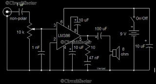
This is a simple low-power audio amplifier circuit capable of producing a power output of 1W. The mono amplifier circuit is built around the LM386 integrated circuit, which operates effectively at low voltages, even below 9V. This low-voltage amplifier...
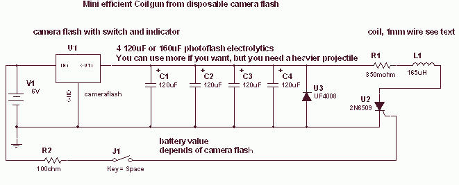
This is a fun and non-dangerous project for those people who like to throw projectiles magnetically. It simply works by placing a ferromagnetic projectile at one end of a coil and pulsing some power in it. The trick is...
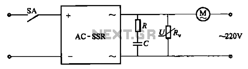
The circuit illustrated in Figure 3-13 is an RC surge absorption circuit that includes a resistor (R) and zinc oxide varistors (such as MY31, MYH12, MYH20 types, etc.), which serve as an overvoltage protection device. The resistance R is...
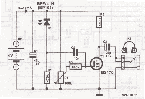
This wireless headphones transmitter ensures quality reception over a distance of 2 meters. The oscillator frequency ranges from 1750 kHz to 3500 kHz, and for the antenna, it... The wireless headphones transmitter operates within a frequency range of 1750 kHz...
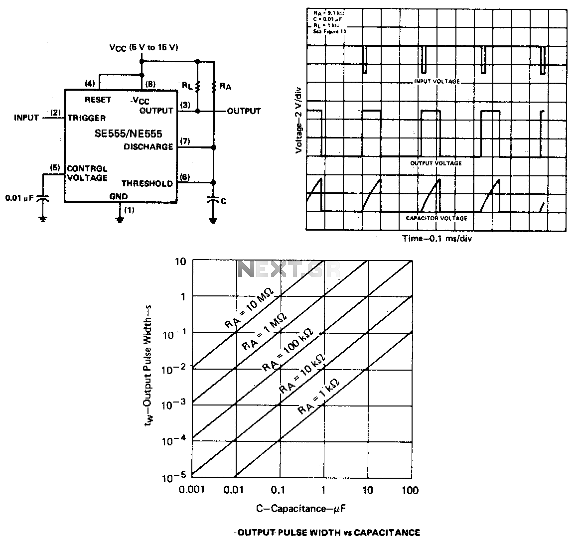
When the output is low, applying a negative-going pulse to the trigger input sets the flip-flop (Q goes low), driving the output high and turning off component 1. Capacitor C is then charged through resistor Ra until the voltage...
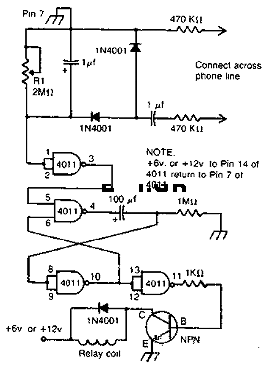
By cross-connecting the telephone ringing circuit, when the phone rings, the circuit activates the relay. It utilizes a delay in contact to drive various devices such as bells, sirens, buzzers, or lights. The telephone ringing circuit is designed to detect...
Warning: include(partials/cookie-banner.php): Failed to open stream: Permission denied in /var/www/html/nextgr/view-circuit.php on line 713
Warning: include(): Failed opening 'partials/cookie-banner.php' for inclusion (include_path='.:/usr/share/php') in /var/www/html/nextgr/view-circuit.php on line 713