
40V dual power supply
The 40V dual power supply circuit is engineered for high efficiency and reliability, suitable for applications requiring a stable power source for amplifiers. The transformer (T1) is selected based on the input voltage and the required output voltage, ensuring that it can handle the power demands of the connected load. The transformer steps down the mains voltage to a lower AC voltage, which is essential for safe operation of the subsequent components.
The bridge rectifier (D1) converts the AC voltage from the transformer into pulsating DC voltage. This rectification process is crucial for providing a usable DC output for the amplifier circuit. The choice of diodes in the bridge rectifier should be based on their current and reverse voltage ratings to ensure reliable operation under load.
Capacitors C1 and C2 are employed for filtering the rectified DC voltage. They smooth out the voltage fluctuations caused by the rectification process, providing a more stable DC output. The capacitance values should be selected based on the load requirements and ripple voltage specifications to maintain performance.
Decoupling capacitors C3 and C4 are included to filter out high-frequency noise from the power supply. These capacitors help stabilize the voltage supply to the amplifier by reducing potential oscillations and ensuring clean power delivery, which is critical for high-fidelity audio applications.
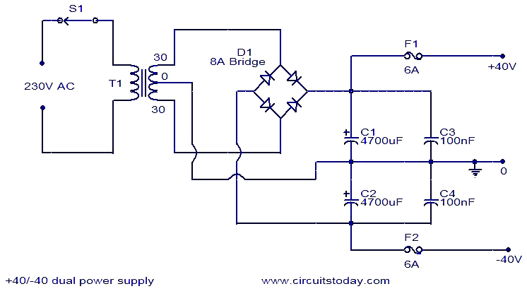
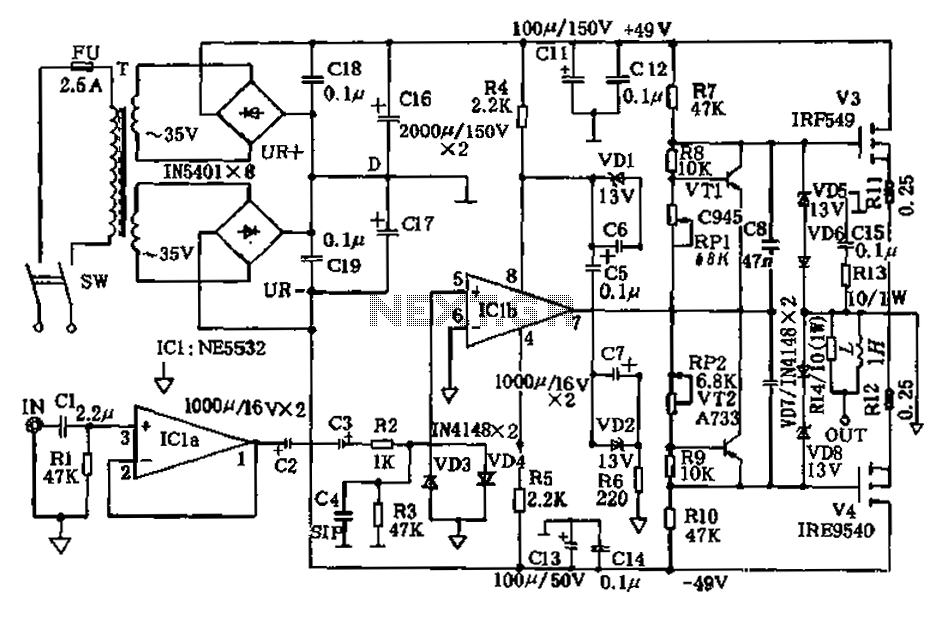
This power supply design is tailored to meet the demands of audio amplification, providing a robust and clean power source necessary for optimal performance of the 150 Watt amplifier circuit. Proper layout and component selection are essential in ensuring that the power supply operates efficiently and reliably under varying load conditions.This 40V dual power supply circuit was designed in response to a request made by Michael from Philippines. His application is to power the 150 Watt amplifier circuit published here. I think this power supply design is adequate for the purpose. The transformer T1 steps down the mains voltage, bridge D1 performs the rectification, C1 and C2 does the
job of filtering. C3 and C4 are decoupling capacitors. We aim to transmit more information by carrying articles. Please send us an E-mail to wanghuali@hqew. net within 15 days if we are involved in the problems of article content, copyright or other problems. We will delete it soon. 🔗 External reference
Related Circuits
This application report presents a potential solution to the telecom plug-in power issue, utilizing a nominal 48 Vdc system bus and a module that requires two low-voltage supply outputs. It includes a comprehensive design methodology for customizing the circuit...
The car cigarette lighter outputs a DC voltage of 12 V, which does not exceed 13.8 V even when the engine is running. A voltage of 19 V is lower than the normally required levels. The car cigarette lighter circuit...
One still designing that it uses in the exit transistor of technology V-mosfet. This transistors to us offer a lot of virtues concerning the simple bipolar transistors, as high speeds, thermic stability, low distortion etc. Beyond this circuit use...
The amplifier circuit presented in this paper introduces a floating power supply aimed at increasing output power. The output power of the amplifier is influenced primarily by the final stage amplifier supply voltage. The circuit's principle is illustrated in...
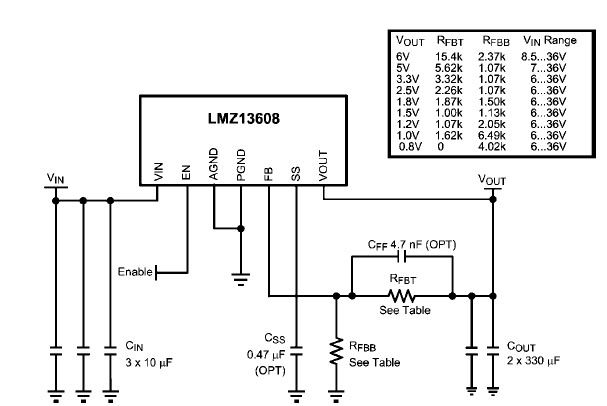
A simple, high-efficiency switching power supply circuit can be designed using the LMZ13608 8A regulator. This regulator offers very high efficiency and requires few external components. It supports a wide input voltage range of 6 to 36 volts and...
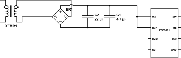
The leads from the transformer to the circuit are quite long (>5m). The 110V side of the transformer has been switched off frequently, which likely caused a spike on the secondary (24V) side. The input pin of the LTC3631...
Warning: include(partials/cookie-banner.php): Failed to open stream: Permission denied in /var/www/html/nextgr/view-circuit.php on line 713
Warning: include(): Failed opening 'partials/cookie-banner.php' for inclusion (include_path='.:/usr/share/php') in /var/www/html/nextgr/view-circuit.php on line 713