
44 Watt Mobile Car Stereo Amplifier
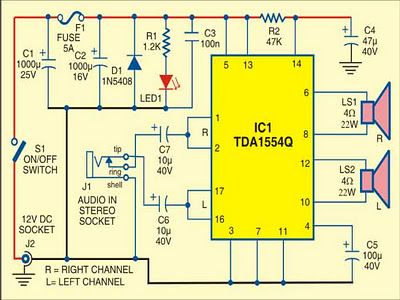
The car audio amplifier circuit utilizes the TDA1554Q, which is well-regarded for its efficiency and performance in automotive applications. This component features a robust design that enables it to deliver high-quality audio while managing heat effectively. The configuration as two bridge amplifiers allows for enhanced audio output, making it suitable for various speaker setups within a vehicle. The protection diode (D1) is critical in automotive applications where incorrect battery connections can occur, thus safeguarding the circuit from damage.
The use of an electrolytic capacitor (C5) for ripple rejection is a common practice in audio amplifier designs, as it ensures cleaner power is delivered to the amplifier, reducing noise and improving sound quality. The additional components (R2 and C4) serve to mitigate unwanted noise during the amplifier's power cycle, which is particularly important in automotive environments where electrical noise can be prevalent.
The compact nature of this design allows for easy integration into vehicles without taking up excessive space, which is a significant advantage in modern automotive design where space is often limited. The choice of an ABS case not only provides durability but also facilitates heat dissipation through vent holes, ensuring the amplifier operates within safe temperature limits.
Overall, this circuit design offers an effective solution for utilizing mobile phones as music sources in vehicles, providing a cost-effective alternative to traditional car audio systems while maintaining high sound quality and user convenience.Using a mobile phone while driving is dangerous. It is also against the law. However, you can use your mobile phone as a powerful music player with the help of a stereo power amplifier. This does away with the need of a sophisticated in-dash car music system. Most mobile phones have a music player that offers a number of features including preset/ manual sound equalisers. They have standard 3. 5mm stereo sockets that allow music to be played through standard stereo headphones/sound amplifiers. Nokia 2700 classic is an example. A car audio amplifier with 3. 5mm socket can be designed and simply connected to the mobile phone output via a shielded cable with suitable connectors/jacks (readymade 3.
5mm male-to-male connector cable is a good alternative). Fig. 1 shows the circuit of car stereo player. It is built around popular single-chip audio power amplifier TDA1554Q (IC1). The TDA1554Q is an integrated class-B power amplifier in a 17-lead single-in-line (SIL) plastic power package. IC TDA1554Q contains four 11W identical amplifiers with differential input stages (two inverting and two non-inverting) and can be used for single-ended or bridge applications.
The gain of each amplifier is fixed at 20 dB. Here it is configured as two 22W stereo bridge amplifiers. The amplifier is powered from the 12V car battery through RCA socket J2. Diode D1 protects against wrong-polarity connection. LED1 indicates the power status. Connect stereo sound signal from the 3. 5mm headset socket of the mobile phone to audio input socket J1. When you play the music from your mobile, IC1 amplifies the input. The output of IC1 is fed to speakers LS1 and LS2 fitted at a suitable place in your car. Electrolytic capacitor C5 connected between pin 4 of IC1 and GND improves the supply-voltage ripple rejection. Components R2 and C4 connected at mute/standby pin (pin 14) of IC1 eliminate the switch on/off plop. The circuit is quite compact. A good-quality heat-sink assembly is crucial for IC1. Fig. 2 shows the stereo socket and stereo jack. Assemble the circuit on a general-purpose PCB and enclose in a suitable cabinet. Small dimensions of the power amplifier make it suitable for being enclosed in a plastic (ABS) case with vent holes.
Signal input socket, speaker output terminals, on/off switch, indicator, fuse holder and power supply socket are best located on the front panel of the enclosure as shown in Fig. 3. 🔗 External reference
Related Circuits
The circuit measures the car water temperature. CA3161 is a counter and 7segment driver to display amount of temperature on 7segments. The temperature sensor is a diode, 1N4148. This is set near of the Car Radiator. To obtain the...
I have had a lot of queries about getting a low power negative supply in cars, to power Linkwitz transform circuits and the like. There is a switchmode converter, but I must admit that it is overkill for what...
This circuit provides a gain of 10 to 15 dB from 400 to 850 MHz, making it particularly effective in scenarios where the television signal is weak. Additionally, the filters can be customized to meet individual user requirements. Construction...
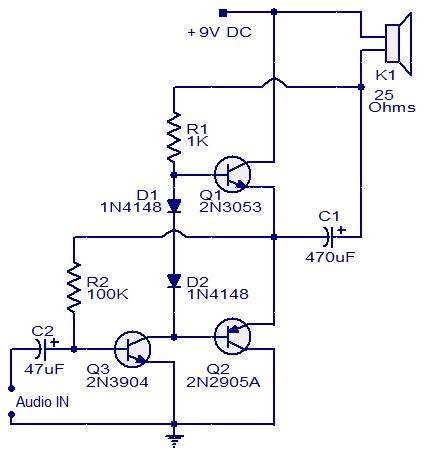
This circuit diagram illustrates a simple three-transistor audio amplifier capable of delivering approximately 100 mW of power to a 25 Ohm speaker. Diodes D1 and D2 provide a constant bias voltage for transistors Q1 and Q2. Transistor Q1 functions...
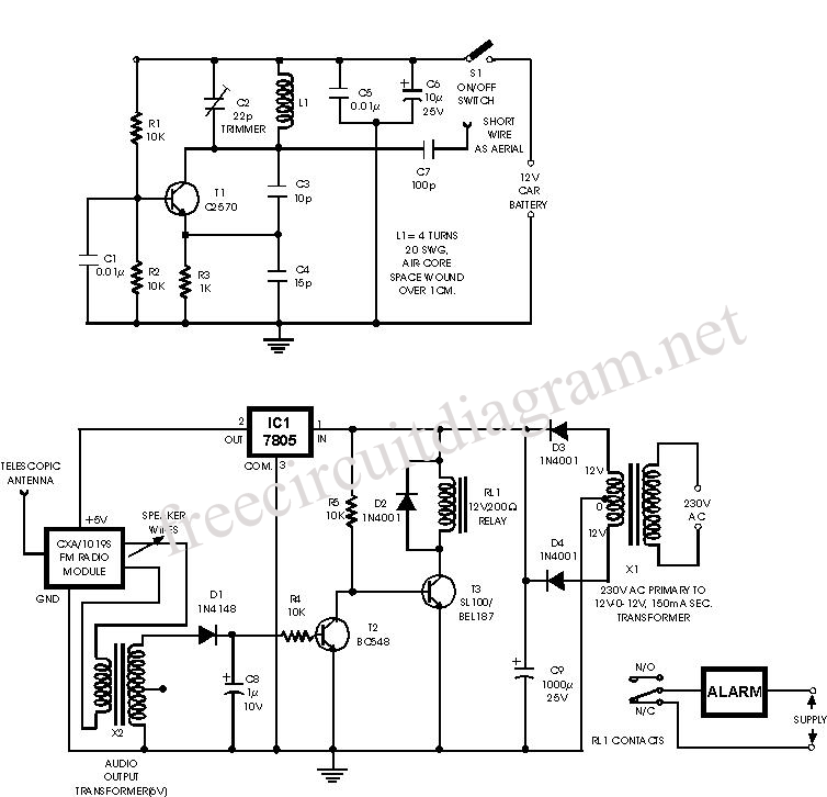
This alarm circuit is an anti-theft wireless alarm that can be used with any vehicle operating on a 6 to 12-volt DC supply system. The mini VHF FM radio-controlled transmitter is installed in the vehicle at night when it...
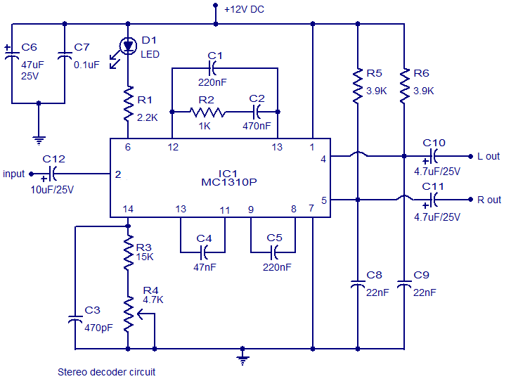
In FM stereo transmission, the left and right audio channels are encoded into sum (left + right) and difference (left - right) signals. This encoding allows mono FM receivers to be compatible with stereo transmissions. The mono receiver reproduces...