
Uhf Tv-Line Amplifier
PARTS LIST:
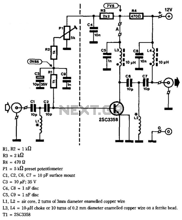
- R1, R2 = 1 kΩ
- R3 = 2 kΩ
- R4 = 470 Ω
- PI = 5 kΩ preset potentiometer
- C1, C2, C6, C7 = 10 pF surface mount
- C3 = 10 µF, 35 V
- C4, C8 = 1 nF disc
- C5, C9 = 1 nF disc
- L1, L2 = air core, 2 turns of 3 mm diameter enameled copper wire
- L3, L4 = 10-ohm choke or 10 turns of 0.2 mm diameter enameled copper wire on a ferrite bead
- T1 = 2SC3358
This circuit is designed for high-frequency applications, particularly in the VHF/UHF range, making it suitable for television signal amplification. The gain specification of 10 to 15 dB is critical for enhancing weak signals, ensuring clearer reception. The use of surface-mount capacitors minimizes board space and allows for a compact design, while the air core inductors provide low-loss filtering characteristics.
The PCB layout should be carefully considered to minimize parasitic inductance and capacitance, which can adversely affect performance at high frequencies. The cut-out for the transistor is essential for proper thermal management, as the device may generate heat during operation. Ground connections for the emitter pins are vital for stability and to reduce noise in the amplified signal.
The use of a watertight enclosure is recommended for outdoor installations, protecting the circuit from environmental factors and ensuring reliability. The power supply design, utilizing a 78L12 regulator, provides a stable voltage with minimal ripple, which is crucial for consistent performance. The choke in the power line helps prevent RF interference from affecting the power supply, maintaining the integrity of the amplified signal.
Calibration procedures should be followed to ensure optimal performance. Adjusting the preset potentiometer PI allows for fine-tuning of the amplifier's gain, directly impacting the quality of the output signal. The collector current measurement provides a means to verify the operational state of the transistor, ensuring it functions within the specified range for effective amplification.
Overall, this circuit design is an efficient solution for enhancing television reception in areas with weak signals, combining simplicity in construction with effective performance characteristics. This circuit offers 10- to 15-dB gain from 400 to 850 MHz and is therefore eminently suitable for situations where th e television signal is weak. Moreover, the filters can be adapted to the individual needs of users. Construction is simplicity itself if the ready-made PC board shown on the next page is used. The tracks should be tinned or silvered for optimum performance and long life. The opening at the center of the board is intended to accommodate the transistor. This device has two emitter pins, both of which should be connected to ground. The drawings show that the board is divided into two by a small piece of tin plate, which should have a small cut-out for the transistor. The input and output terminals are made from small cable clamps and M3 nuts and bolts. One side of disc capacitors C4, C5, C8, and C9 is soldered direct to the board. Input and output capacitors, C1/C2 and C6/C7 respectively are surface-mount types. C1/C2/L1 form an input filter and C6/C7/L2 form an output filter. The value of the capacitors might have to be lowered to 3.9 pF to obtain the correct frequency range.
The amplifier can be housed in a watertight case and then mounted near the antenna at the top of the mast (if used). The power is obtained from a simple stabilized 12-V supply: a mains adapter with a 78L12 will do nicely.
This can be kept indoors, of course. The amplifier can be powered via the coaxial feeder cable, for which purpose a 10- to 100- choke is inserted in the supply line. Calibrating the amplifier is straightforward: set PI to the center of its travel and then adjust it for optimum picture quality.
In practice, the collector current of the transistor is then 5 to 15 mA. This may be checked by temporarily replacing jump lead A by one suitable meter. PARTS LIST Rl, R2 = 1 KOhmhm R3 = 2 ki2 R4 = 470 PI = 5 preset potentiometer CI, C2, C6, C7 = 10 pF surface mount C3 = 10 -, 35 V C4, C8 = 1 nF disc C5, C9 « 1 nF disc LI, L2 = air core, 2 turns of 3mm diameter enamelled copper wire L3, L4 = 10- choke or 10 turns of 0.2 mm diameter enamelled copper wire on a ferrite bead. T1 = 2SC3358 🔗 External reference
Related Circuits
For capacitor C3, a 100pF capacitor is placed across resistor R2. The circuit functions similarly to previous configurations, although no explanation is provided. The purpose of this component may be self-evident to experienced users, but it may not be...
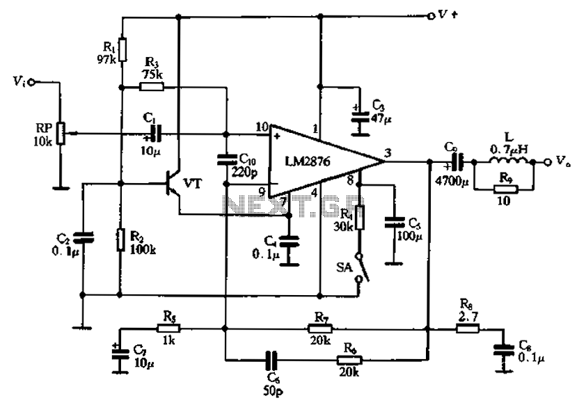
A single power amplifier circuit using the LM2876 IC is designed. An external transistor (VTf) is configured to form an emitter follower, which provides a neutral level (7 feet) for the LM2876, ensuring reliable noise suppression in the circuit...
To omit the balance control when using separate potentiometers for the volume controls, refer to the balance control notes on the 7-tube output amplifier page. A schematic was utilized to build a modified version with separate bass and treble...
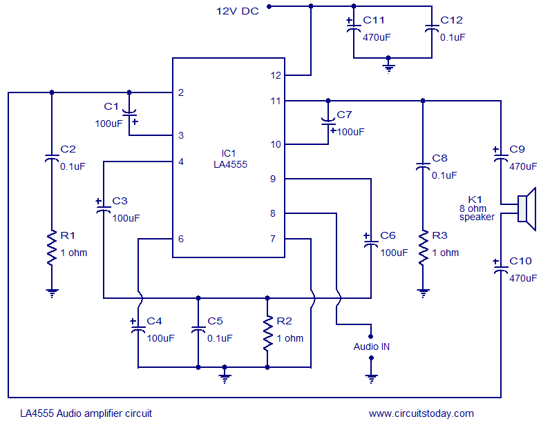
The LA4550 audio amplifier operates in a BTL (Bridge-Tied Load) configuration. This amplifier is capable of delivering 4W into an 8-ohm load when powered by a 12V power supply. The LA4550 is designed for audio amplification applications, particularly in situations...
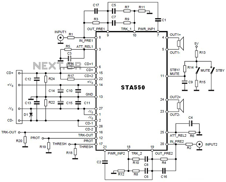
This is a 2 x 70W audio power amplifier circuit built using a single IC STA550. The amplifier circuit requires a few external components, primarily resistors and capacitors, and is straightforward to design. The STA550 audio amplifier can provide...
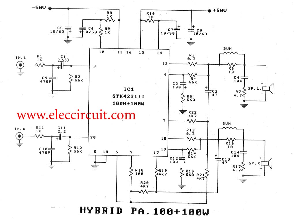
To create a 100-watt OCL audio amplifier circuit, consider using this design. It incorporates the STK4231 integrated circuit, which is a compact and cost-effective solution. The STK4231 is a hybrid IC from Sanyo, belonging to the STK4201II series, capable...