
Stereo Decoder
The stereo decoder circuit utilizing the MC1310P is designed to efficiently decode the composite FM stereo signal into its individual left and right audio channels. The process begins with the composite audio signal, which contains both the sum and difference information of the left and right channels. Upon entering the IC at pin 2, the signal is first decoupled by capacitor C12, ensuring that any power supply noise does not interfere with the decoding process.
Power supply filtering is achieved using capacitors C6 and C7, which stabilize the voltage levels supplied to the IC, enhancing its performance and reliability. The internal oscillator of the MC1310P is critical for timing and synchronization; it is formed by capacitor C3 and resistors R3 and R4, providing the necessary oscillation frequency that the decoder requires for accurate processing.
The loop filter, comprised of resistor R2 and capacitors C1 and C2, plays a crucial role in maintaining the stability of the decoded output signals. It helps to smooth out any fluctuations in the output, ensuring that the audio quality remains high. The inclusion of diode D1 as an indicator LED provides a visual cue that the decoder is operational, while resistor R1 serves to limit the current through the LED, preventing damage to the component.
The stereo outputs, which are the decoded left and right channels, are available at pins 4 and 5 of the IC. Capacitors C10 and C11 act as DC decoupling capacitors, isolating the audio signals from any DC offset, which is crucial for driving subsequent audio amplification stages without distortion.
Overall, the MC1310P stereo decoder circuit is an effective solution for recovering stereo audio from FM broadcasts, ensuring compatibility with both stereo and mono receivers while maintaining audio fidelity.In FM stereo transmission left and right channels are algebraically encoded into sum (left + right) and difference (left-right) signals. This is done in order to make the mono FM receivers compatible with the stereo transmission. The mono receiver will reproduce the summed left and right channel and the listener will hear both these channels through a single loud speaker.
Stereo decoder is a circuit which is used in stereo FM receivers in order to recover the left and right channel information from the composite transmission signal. This task is achieved by adding the difference signal to the summed signal to recover left channel and subtracting the difference signal from the summed signal to recover the right channel.
The circuit diagram of a stereo decoder using MC1310P IC from Motorola is shown below. MC1310P is an integrated stereo decoder IC chip which is available in 14 pin DIL plastic package. In the circuit composite signal if fed to the input pin (pin2) of the IC through decoupling capacitor C12. Capacitors C6 and C7 do the job of power supply filtering. Capacitor C3 plus Resistors R3 and R4 forms the RC for the ICs internal oscillator circuit. Resistor R2 plus capacitors C1 and C2 forms a loop filter. D1 is an indicator LED and R1 limits the current through it. The decoded left and right stereo outputs are available at pins 4 and 5 respectively. C10 and C11 are the DC decoupling capacitors for the left and right outputs. Be the first of your friends to get free diy electronics projects, circuits diagrams, hacks, mods, gadgets & gizmo automatically each time we publish.
Your email address & privacy are safe with us ! 🔗 External reference
Related Circuits
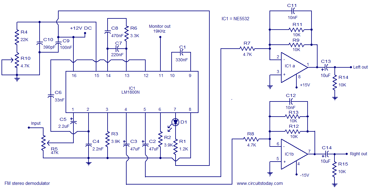
The following circuit illustrates the LM1800 IC Integrated FM Stereo Demodulator Circuit. Features include excellent sound quality and high-quality FM stereo. The LM1800 Integrated Circuit (IC) serves as a highly effective FM stereo demodulator, designed to deliver superior audio performance...
The following schematic illustrates a 5.8W stereo power amplifier utilizing the Samsung IC KA2211. Each channel delivers a power output of 5.8W, resulting in a maximum combined output of 2 x 5.8W. The KA2211 is a dual audio power...
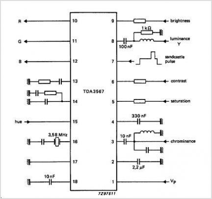
The TDA3592A transcoder circuit converts SECAM input signals into true PAL signals and can be used in combination with all types of PAL decoders by NXP Semiconductors. The TDA3592A is a versatile transcoder integrated circuit designed to facilitate the conversion...
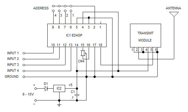
The Glolab ED4GP microprocessor-based Encoder/Decoder is designed for use with wireless modules, infrared remote controls, and other devices that operate with serial input and output data. It can function as either an encoder or a decoder by connecting pin...
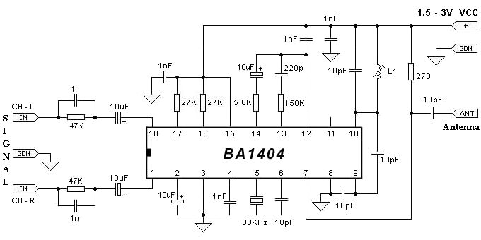
The BA1404 FM stereo modulator IC includes all the necessary components to design a simple, high-efficiency stereo transmitter circuit. It features a stereo modulator that generates composite stereo signals, an FM modulator for creating FM signals, and an RF...
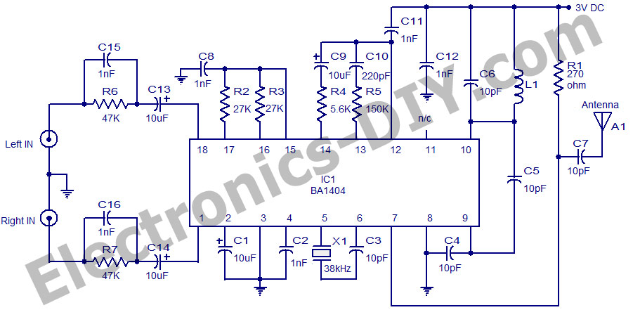
The circuit utilizes the BA1404 integrated circuit from ROHM Semiconductors. The BA1404 is a monolithic FM stereo modulator that incorporates a stereo modulator, FM modulator, and RF amplifier circuitry. This FM transmitter operates within the frequency range of 76...
Warning: include(partials/cookie-banner.php): Failed to open stream: Permission denied in /var/www/html/nextgr/view-circuit.php on line 713
Warning: include(): Failed opening 'partials/cookie-banner.php' for inclusion (include_path='.:/usr/share/php') in /var/www/html/nextgr/view-circuit.php on line 713