
Neon high-voltage power supply circuit diagram
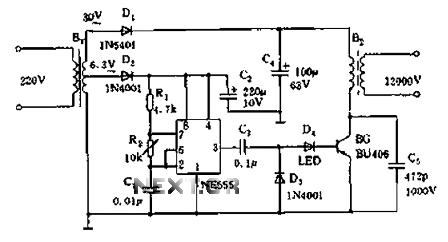
The neon voltage power supply circuit utilizes the NE555 timer in astable mode to produce a square wave output, which is essential for driving the subsequent components. The oscillation frequency, determined by the values of resistors R1 and R2, along with capacitor C1, can be fine-tuned to optimize the performance of the neon tube lighting. The output from pin 3 is a square wave that transitions between high and low states, providing the necessary drive signal for the transistor.
The transistor (BG) serves as a switch, amplifying the current from the NE555 output to drive the step-up transformer. When the transistor is turned on, current flows through the primary winding of the transformer, inducing a high voltage in the secondary winding due to the principles of electromagnetic induction. This high voltage is crucial for ionizing the gas within the neon tube, allowing it to emit light.
The LED in the circuit acts as a visual indicator of the operational status of the power supply. Its brightness correlates with the duty cycle of the NE555 output, providing a straightforward means of monitoring the circuit's performance. If the LED is dim or not lit, it indicates that the transistor may not be switching correctly, or there may be an issue with the circuit.
The inclusion of diode D1 is vital for protecting the circuit from back EMF generated when the transformer is de-energized. This diode ensures that the current flows in the correct direction and prevents damage to the transistor and other components.
Overall, this neon voltage power supply circuit is efficient for driving neon tubes, with the ability to adjust the output voltage to accommodate various tube lengths. The design is robust and can be adapted for different applications requiring high-voltage, low-current outputs. As shown neon voltage power supply circuit. Its production is simple, stable output power and other characteristics. Circuit Principle: The core element of this circuit is the time base NE555 circuit which generates a high-frequency oscillation signal of 15 ~ 20kHz, high frequency can be adjusted R2. Drive signal output by 3 feet, after sub-circuit is C3, D1, LED component, so that high-power tube BG work in the C state.
The intensity of the drive signal can be directly observed it according to the brightness of LED, driven by power tube is turned on and off, flowing through the step-up transformer primary winding current B2 size variations occur, then in the B2 sub-polar high voltage generates a high-frequency current, for neon tubes work. R2 can adjust the output voltage up. BG connected between the collector and ground capacitor C5 can be omitted or open, to prevent anti-peak voltage produced by the B2 breakdown BG, under normal circumstances, the power output of the circuit can drive 3 ~ 6m neon tube lighting.
Related Circuits
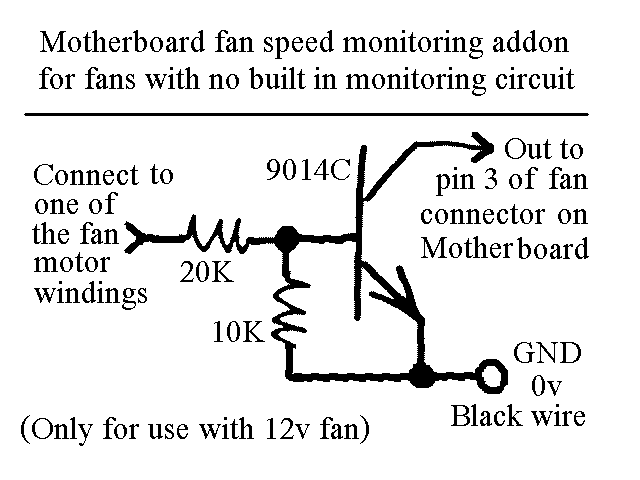
You will find this identical circuit inside most 3 wire computer fans with speed monitoring output to the motherboard. Peel off the sticker from the fan hub in order to access a motor winding pin for connecting up the...
The power supply has been simplified. Power transformers and rectifiers have been omitted, and some components from the MOSFET voltage regulator circuits have been removed, including 1N5242 zener diodes between the source and gate and 10k resistors in series...
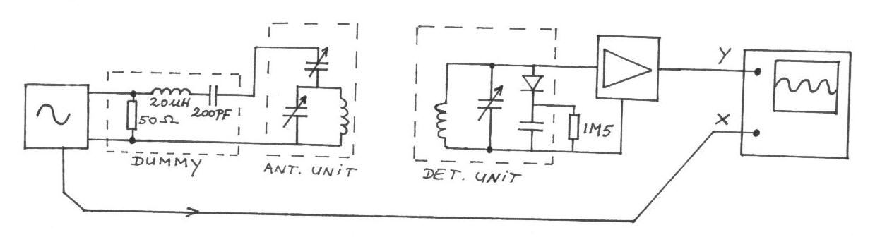
The frequency remains constant, oscillating between two predetermined values. On the oscilloscope display, a frequency spectrum is observed, showcasing the response curves of the two circuits. The input voltage of the receiver is 0.1 Volt peak-to-peak, while the voltage...
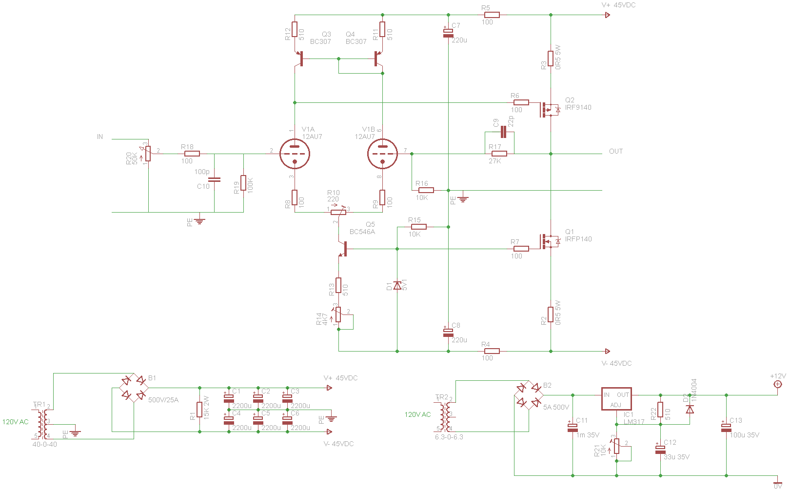
A tube/MOSFET hybrid power amplifier is being constructed based on a circuit published in AudioXpress by Cozza (May 2001), which is derived from a design by Borbely. The tube/MOSFET hybrid power amplifier integrates the warm, rich sound characteristics of vacuum...
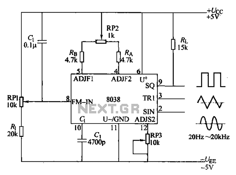
The audio function generator integrated circuit ICL8038 is capable of producing square waves, triangle waves, and sine waves. The electrical resistance and potentiometer RP1 are utilized to determine the 8-pin DC potential Ua, which is typically set to 2Ucr/3....
This type of sensor switch is ideal for creating touch-operated bells and buzzers in small toys, which function for a limited duration before automatically shutting off. The trigger's input impedance is very high, allowing the touch sensor switch to...