
Implementing An Ultralow-power Thermostat With Slope A/d Conversion

No description available.
Related Circuits
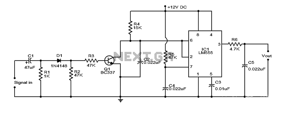
This document provides an overview of a simple circuit diagram for frequency (F and V) voltage conversion. It describes a digital frequency meter circuit primarily based on the LM555 timer IC, which is commonly used in various applications, including...
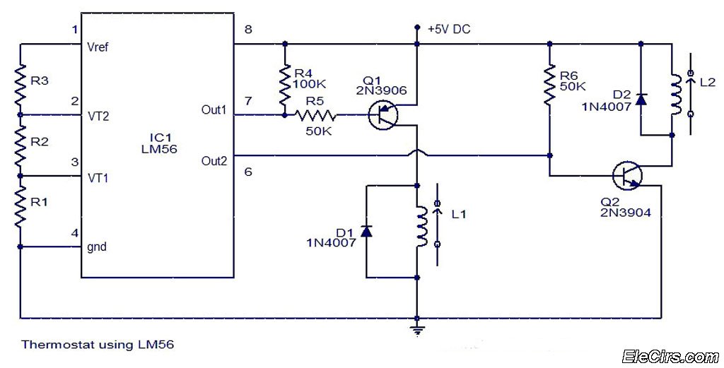
The LM56 Thermostat Project Circuit Diagram includes a schematic for the LM56 thermostat. The values of resistors R1, R2, and R3, which determine the required trip points VT1 and VT2, can be calculated using the following equations: VT1 =...
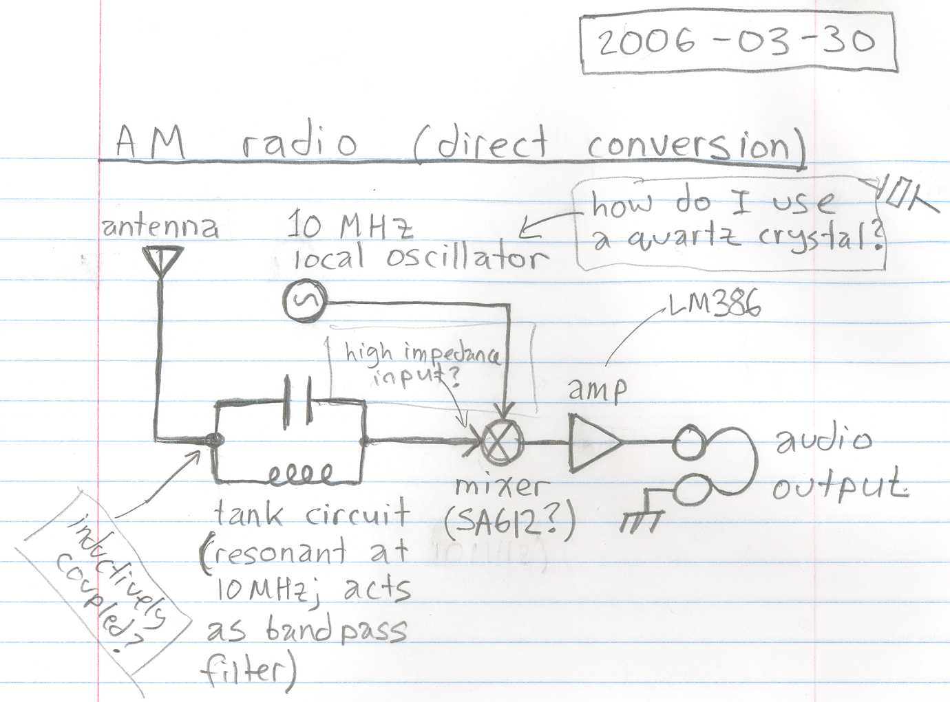
A basic design for a direct conversion AM radio receiver is being developed. "Direct conversion" refers to the technique of utilizing a mixer to shift the radio frequency signal down to baseband audio frequencies. There are uncertainties regarding the...

The thermostat electric circuit operates as depicted in the figure. It has three settings: off, low power (Lo), and high power (Peru HL). When the DIP switch SA is set to the Lo position, 220V AC is directed through...
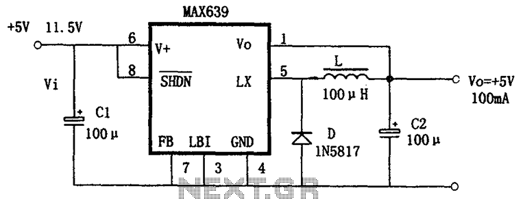
The circuit is based on the MAX639, which is a high-efficiency, step-down DC/DC converter. It operates with an input voltage range of 5.5V to 11.5V, providing a fixed output voltage of +5V or an adjustable voltage. The output current...
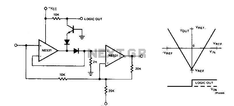
The cyclic converter is composed of a series of identical stages, each stage detecting the polarity of the input. The reference voltage, V_REF, is subtracted from the double entry, and the remaining value is processed if the polarity is...