
LCD Interfacing with 8051

The interfacing of a 16x2 Liquid Crystal Display (LCD) with the 8051 microcontroller is a common practice in embedded systems design, allowing for the visual output of data. The 16x2 LCD consists of two rows with 16 characters each, making it suitable for displaying alphanumeric information.
To successfully interface the LCD with the 8051 microcontroller, the following components and steps are required:
1. **Components Required:**
- 8051 Microcontroller (e.g., AT89C51)
- 16x2 LCD
- Resistors (typically 220Ω for backlight)
- Potentiometer (10kΩ for contrast adjustment)
- Breadboard and jumper wires
- Power supply (typically 5V)
2. **Pin Configuration:**
The 16x2 LCD has 16 pins, which need to be connected appropriately to the 8051. The essential pins include:
- VSS (Ground)
- VDD (Power supply, +5V)
- V0 (Contrast adjustment, connected to the wiper of the potentiometer)
- RS (Register Select, connected to a GPIO pin of the microcontroller)
- RW (Read/Write, typically grounded for write operations)
- E (Enable, connected to a GPIO pin of the microcontroller)
- Data pins (D0 to D7, typically connected to GPIO pins of the microcontroller)
3. **Circuit Connections:**
The microcontroller's GPIO pins will be configured as outputs for data transmission to the LCD. The RS and E pins control the mode of operation (command or data) and the timing of data transmission, respectively. The data pins can be connected in either 4-bit or 8-bit mode, with 4-bit mode being more common to minimize pin usage.
4. **Programming:**
The source code for interfacing the LCD with the 8051 microcontroller typically includes functions for initializing the LCD, sending commands, and writing data to be displayed. The initialization sequence involves setting the LCD to 4-bit mode, configuring the display settings, and clearing the screen. The code will utilize delay functions to ensure proper timing between commands and data writes.
5. **Testing:**
After establishing the connections and uploading the code to the microcontroller, the functionality can be tested by sending various characters and strings to the LCD. Observing the display for any anomalies will help in troubleshooting potential issues such as incorrect wiring or timing errors.
This comprehensive approach to interfacing a 16x2 LCD with the 8051 microcontroller provides a solid foundation for further exploration into embedded system applications, enhancing the capability to present information visually in various projects.Learn how to interface LCD 16x2 with 8051. Download free source code on LCD interfacing with 8051 Microcontroller 🔗 External reference
Related Circuits
In the production of LCD projectors, the primary factor threatening the lifespan of the LCD screen is the temperature generated by halogen lamps. The multi-function controller designed by this circuit is highly effective for protecting liquid crystal projectors. The...
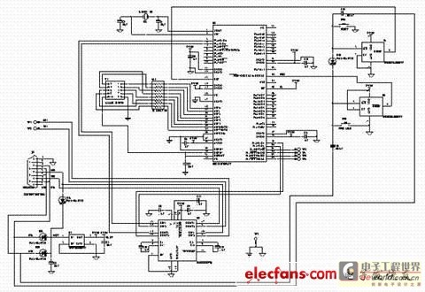
This text discusses the MSC1210 microcontroller as the core of a high-accuracy temperature measurement system, which includes signal processing and communication capabilities. The system is designed for easy expansion, allowing for accurate measurements and fast data acquisition. The hardware...
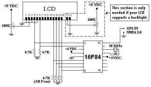
This is a project that I started back late 2003 when I just starting to learn PIC programming. I wanted to building something that actually did something useful. This project is based on a PIC16F84. I actually came up...
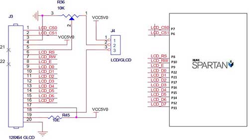
The Spartan-6 board features a 2x16 LCD, as illustrated in the accompanying figure. This 2x16 character LCD interface card supports both 4-bit and 8-bit modes, and it includes a facility for contrast adjustment via a trim potentiometer. In the...
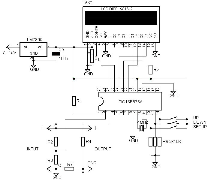
Voltmeters and ammeters with a PIC microcontroller can be utilized to measure voltage and current simultaneously. The configuration of voltmeters and ammeters using the PIC16F876A serves as a data processor for voltage and current measurements. This circuit employs a...
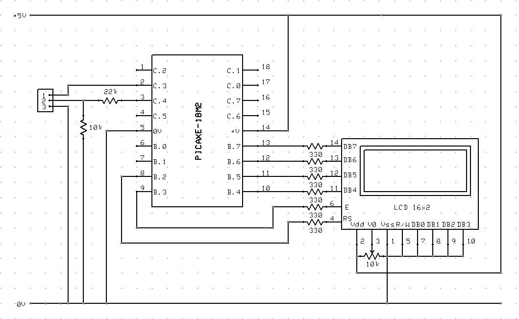
The circuit diagram and code on how to connect a 16x2 LCD to a PICAXE-18M2 microcontroller. The circuit involves interfacing a 16x2 Liquid Crystal Display (LCD) with a PICAXE-18M2 microcontroller. The 16x2 LCD is a popular display module that can...