
5 Band Graphic Equalizer circuit

The described graphic equalizer circuit utilizes five frequency bands to adjust the tonal quality of audio signals. The selection of transistors over integrated circuits is significant, as transistors can offer enhanced performance characteristics, such as lower distortion levels and improved dynamic range. By operating at a power supply voltage of +/- 24V DC, the circuit is capable of handling higher signal levels without distortion, which is crucial for professional audio applications where fidelity is paramount.
The inclusion of switch S1 provides functional versatility, allowing the user to bypass the equalizer section when desired. This feature is particularly useful for situations where a pure audio signal is required, enabling the signal to pass through the circuit without any modifications.
In terms of design, the five-band equalizer typically consists of a series of band-pass filters, each tuned to a specific frequency range. These filters may be implemented using transistor-based amplifiers configured to adjust gain levels for their respective bands. The output of each filter can be mixed back together to produce a composite audio signal that reflects the applied equalization.
To further enhance the performance of the equalizer, attention must be given to the layout of the circuit board, ensuring minimal noise interference and optimal signal integrity. Proper decoupling of the power supply lines and careful placement of components can significantly improve the overall performance of the circuit.
In summary, this graphic equalizer circuit represents an advanced approach to audio processing, utilizing transistor technology and a higher voltage power supply to achieve superior sound quality and flexibility in audio signal manipulation.Other one unit of graphic EQ. five bands. The basic difference with the other circuits is, that I use instead of IC, transistor and the power supply, go up in +/- 24V DC, ensuring low distortion and bigger margins of overloading. With switch S1, we can isolate the EQ. inside or except operation, leaving the musical signal to pass without no alteration.. 🔗 External reference
Related Circuits
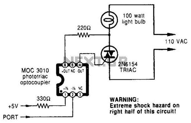
A microcomputer-to-triac interface utilizes a phototriac optoisolator to safely isolate logic signals, allowing direct control of high-power loads. This circuit can function as either an on/off switch or a proportional phase control, depending on the input waveforms and the...
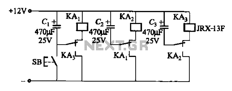
The relay control allows for multiple pairs of contacts to be connected in parallel, enabling the circuit to handle a large lamp power. The design is straightforward; by simply changing the capacitance of the capacitor, different flash frequencies can...
The circuit diagram is designed for precise control of DC motors. It converts DC voltage into a series of pulses, where the duration of each pulse... The circuit utilizes a pulse-width modulation (PWM) technique to regulate the speed and torque...
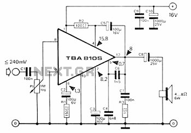
This circuit is a 7 Watt audio amplifier that is simple and easy to construct. It utilizes the TBA810 as the primary component, supported by a few passive components. The amplifier operates effectively, and the necessary kits and components...
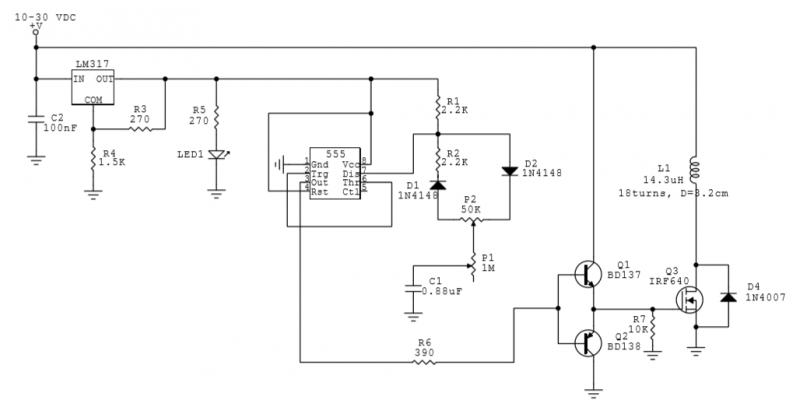
This circuit utilizes a 555 Integrated Circuit (IC) to generate a pulsed magnetic field, which can be employed for pulsed electromagnetic field (PEMF) therapy. The human body is affected by natural magnetic fields, including the Earth's magnetic field, geomagnetic...
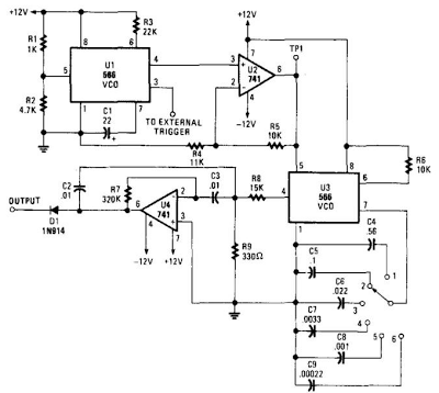
When this circuit is connected to a filter and an oscilloscope, the oscilloscope displays the filter's frequency response. A frequency that sweeps from low to high is applied to a filter. The oscilloscope is triggered by the start of...