
5-Band Graphic Equalizer with LA3600

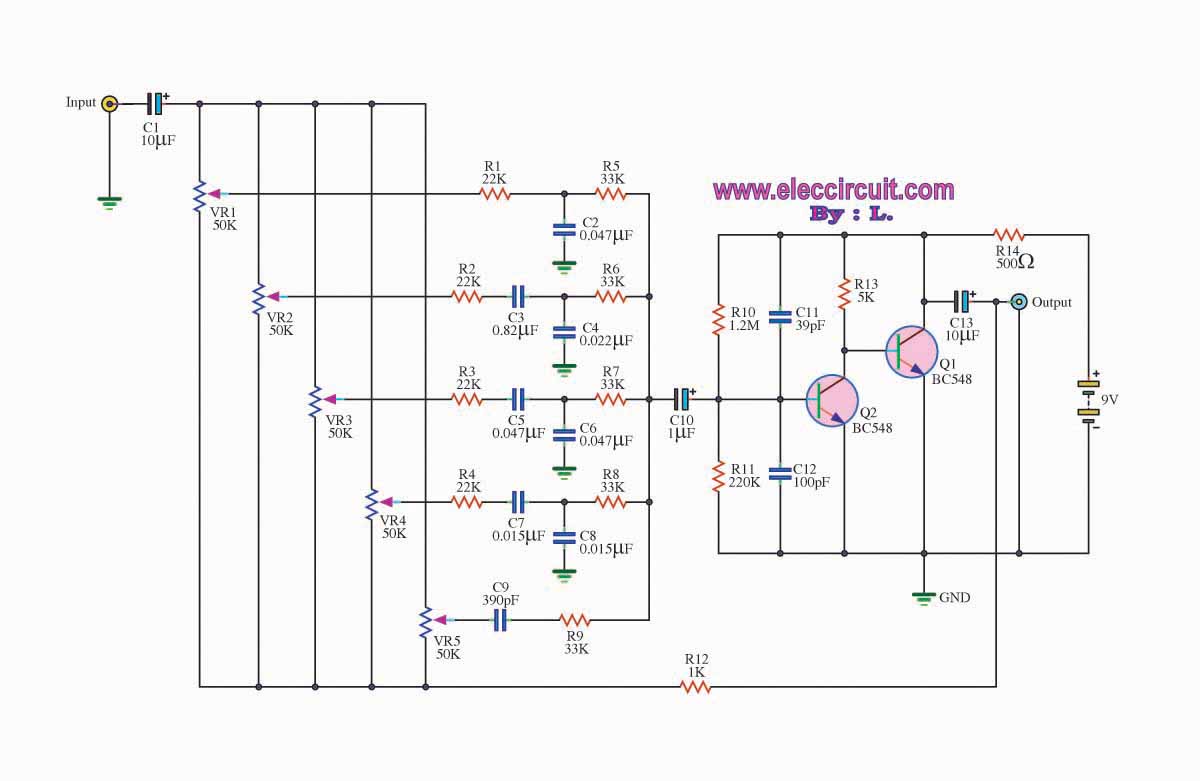
The 5-band graphic equalizer circuit utilizing the LA3600 integrated circuit is designed to enhance audio performance by allowing users to adjust frequency response across five distinct bands. This circuit is particularly suitable for portable audio devices, including component stereos, tape recorders, radio-cassette recorders, and car stereos, making it versatile for various audio applications.
The LA3600 IC integrates a single operational amplifier, which simplifies the design and reduces component count. The equalizer can be configured by connecting external capacitors and variable resistors that define the resonance frequencies for each band. This flexibility enables precise tuning of the audio signal, allowing users to boost or cut specific frequency ranges according to their preferences.
For applications requiring more than five bands, the circuit can be expanded by connecting two LA3600 ICs in series, facilitating the creation of a multiband equalizer with six to ten bands. This modular approach not only enhances functionality but also maintains the overall stability and performance of the equalizer.
The circuit exhibits high stability when driving capacitive loads, ensuring consistent audio quality without distortion. The operational voltage range of the LA3600 is between 5V and 15V, with a maximum supply voltage of 20V. It is critical to adhere to these voltage specifications to prevent damage to the IC. Care should be taken during assembly to avoid unintentional short circuits between pins, which could lead to breakdown or degradation of the integrated circuit. Proper mounting techniques and careful inspection for solder bridges are essential to ensure reliable operation of the equalizer circuit.This complete high quality, low noise 5-BAND GRAPHIC EQUALIZER circuit is based around Monolithic Linear integrated circuit LA3600 manufactured by SANYO. This circuit is very easy to build and has good Quality. You can use it with Portable component stereos, tape-recorders, radio-cassette recorders, car stereos etc...
It is On-chip one operational amplifier. 5-band graphic equalizer for one channel can be formed easily by externally connecting capacitors and variable resistors which fix fo (resonance frequency). Series connection of two LA3600?s makes multiband (6 to 10 bands) available. It is Highly stable to capacitive load. Maximum supply voltage VCC max 20V must not be exceeded. The operating voltage is in the range of 5 to 15V. Application of power with the pin-to-pin spaces shorted causes breakdown or deterioration of the IC to occur.
When mounting the IC on the board or applying power, make sure that the pin-to-pin spaces are not shorted with solder, etc. 🔗 External reference
Related Circuits
Designed for communications use, this equalizer circuit utilizes a Mitsubishi M5226P audio equalizer IC to modify frequency response. It operates with a supply voltage ranging from 9 to 20 V. Capacitors C6 through C16 are polyester film capacitors with...
The graphic equalizer circuit is designed to adjust frequency response in audio systems. Certain audio frequency responses may not be smooth. The graphic equalizer circuit functions by providing the ability to adjust specific frequency bands of an audio signal, allowing...
The equaliser under discussion is specifically engineered to function as a preamp for musical instruments, notably the guitar, bass, and keyboard. This design sets it apart from the majority of conventional graphic equalisers, which typically offer a range from fully...
Schematic diagram. A presentation of the element-by-element relationship of all parts of a system. A schematic diagram serves as a crucial tool in electronic design and engineering, representing the interconnections and relationships between various components within a system. It provides...
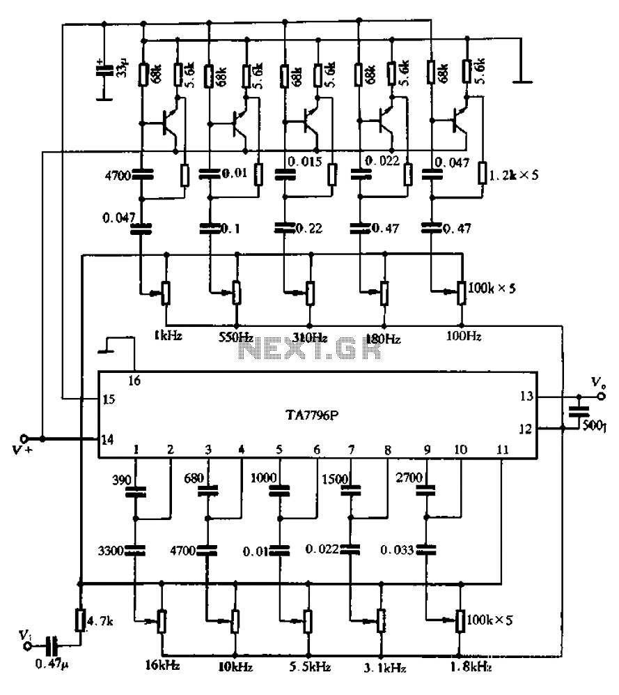
Another application example is presented. It utilizes the TA7796 IC along with five external transistors to create a ten-band equalizer circuit. The lowest center frequency of the equalizer is set at 100 Hz, while the highest center frequency of...
This 10-band graphic equalizer circuit utilizes a single chip, the IC TL074, to create a 5-band graphic equalizer suitable for high-fidelity audio systems. The 5-band graphic equalizer is particularly effective for radio-cassette players and car stereos. Key features include...