
schematic diagram graphic arts
A schematic diagram serves as a crucial tool in electronic design and engineering, representing the interconnections and relationships between various components within a system. It provides a visual framework that illustrates how each element, such as resistors, capacitors, transistors, and integrated circuits, interacts within the overall circuit.
In a typical schematic, symbols are used to denote different electronic components, and lines represent the electrical connections between them. This representation allows engineers and technicians to easily understand the functionality and layout of the circuit without the need for physical assembly.
Schematic diagrams are essential for troubleshooting, as they enable users to trace signals through the circuit and identify potential issues. Additionally, they serve as a reference during the manufacturing process, ensuring that all components are correctly placed and connected according to the design specifications.
The clarity of a schematic diagram is paramount; it should be organized logically, with components arranged to minimize confusion. Labels and values for each component are typically included to provide additional context, such as resistance values for resistors or capacitance for capacitors. By adhering to standardized symbols and conventions, schematic diagrams facilitate communication among engineers and ensure consistency across designs.
Overall, a well-crafted schematic diagram is an indispensable element in the development and documentation of electronic systems, enabling efficient design, analysis, and maintenance.schematic diagram. A presentation of the element-by-element relationship of all parts of a system.. 🔗 External reference
Related Circuits
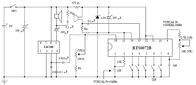
This voice changer circuit diagram is an electronic project developed using the RTS0072B single-chip CMOS LSI, specifically designed for voice-changing applications. It can transpose or distort one voice into another by encoding the input audio signals at normal speed...
C0QBmk~%24(KGrHqIOKkIEq4M%2Bu,)1BK2zHH580Q~~_35.gif)
This time, information will be shared about the schematics of radios, specifically the schematic of a programmer radio, along with the latest information available on Onmilwiki. The schematic of a programmer radio typically includes various components essential for its operation,...
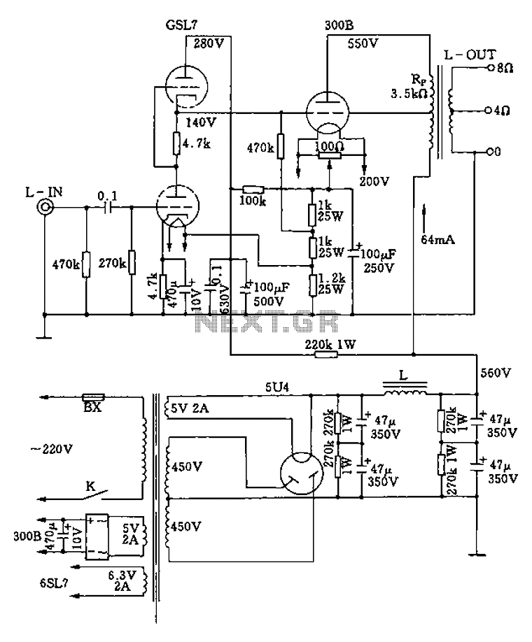
The 300B tube single-ended Class A amplifier circuit is as follows: The 300B tube single-ended Class A amplifier is a high-fidelity audio amplification circuit that utilizes a 300B vacuum tube as the primary amplification element. This design is characterized by...
The circuit consists of a lag comparator with amplifier A1 and an inverting integrator A2. The charging and discharging time constant is determined by the integral resistors (R1 + RP1) and the capacitor C1. Diodes VD1 to VD5 form...
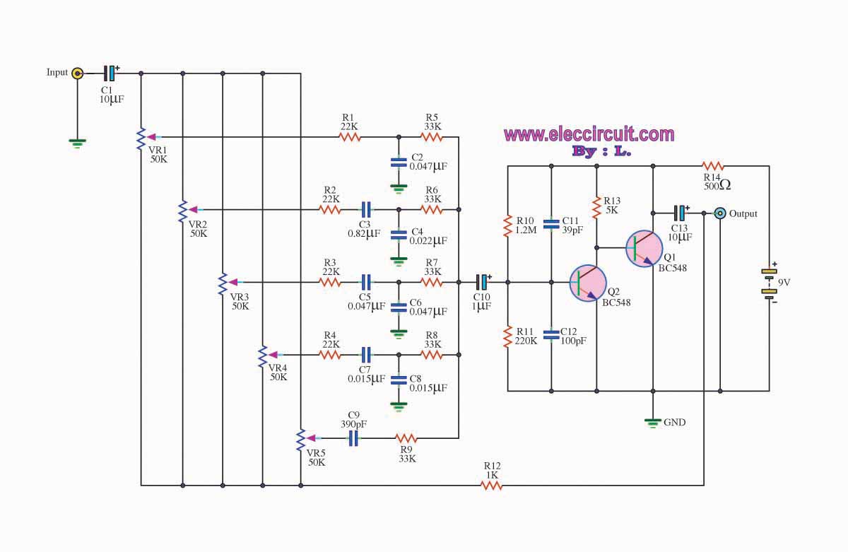
The graphic equalizer circuit is designed to adjust frequency response in audio systems. Certain audio frequency responses may not be smooth. The graphic equalizer circuit functions by providing the ability to adjust specific frequency bands of an audio signal, allowing...
The circuit diagram of a TV antenna is sourced from the technical information provided by Chinaicmart. For more detailed information or additional circuit designs, further inquiry may be necessary. The circuit diagram for a TV antenna typically consists of several...