
Audio Equalizer Circuit
The equalizer circuit is specifically engineered to enhance audio signals in communication applications by allowing precise adjustments to the frequency response. The Mitsubishi M5226P IC serves as the core component, providing the necessary processing capabilities for audio equalization. This IC is designed to handle a wide range of frequencies, making it suitable for various audio applications.
The power supply requirement of 9 to 20 V ensures compatibility with standard communication equipment, allowing for flexibility in integration with existing systems. The choice of polyester film capacitors (C6 through C16) contributes to the circuit's stability and performance. These capacitors are known for their low distortion and high-frequency response, which is essential for maintaining audio quality in communication systems.
In addition to the capacitors, the circuit may include resistors and other passive components that support the functionality of the equalizer. The layout of the circuit should be optimized to minimize noise and interference, ensuring that the audio signal remains clear and undistorted. Proper grounding and shielding techniques should also be employed to enhance the overall performance of the circuit in real-world applications.
Overall, this equalizer circuit represents a robust solution for audio processing in communication systems, leveraging the capabilities of the Mitsubishi M5226P IC and high-quality passive components to deliver superior audio performance.Designed for communications use, this equalizer circuit uses a Mitsubishi M5226P audio equalizer IC to adjust frequency response. It runs from a 9 to 20 V supply. C6 through C16 are polyester film capacitors of +- 5% tolerance. (QST, 🔗 External reference
Related Circuits
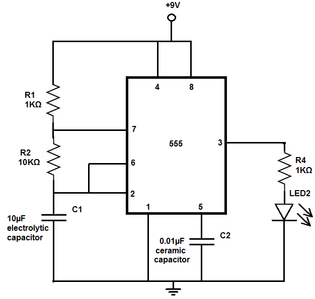
The 555 timer chip is a versatile integrated circuit (IC) that, when connected correctly, can generate pulses of current at specific intervals determined by a resistor-capacitor (RC) network. In this mode, the LED does not remain constantly lit; it...
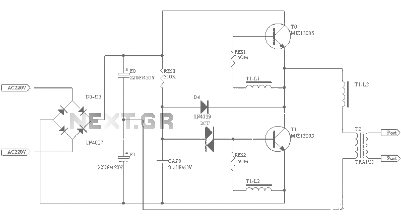
A small (2 to 3 meters) neon electronic transformer circuit diagram is provided below. The described circuit diagram is intended for use with neon lighting systems, specifically those requiring a transformer to operate efficiently within a range of 2 to...
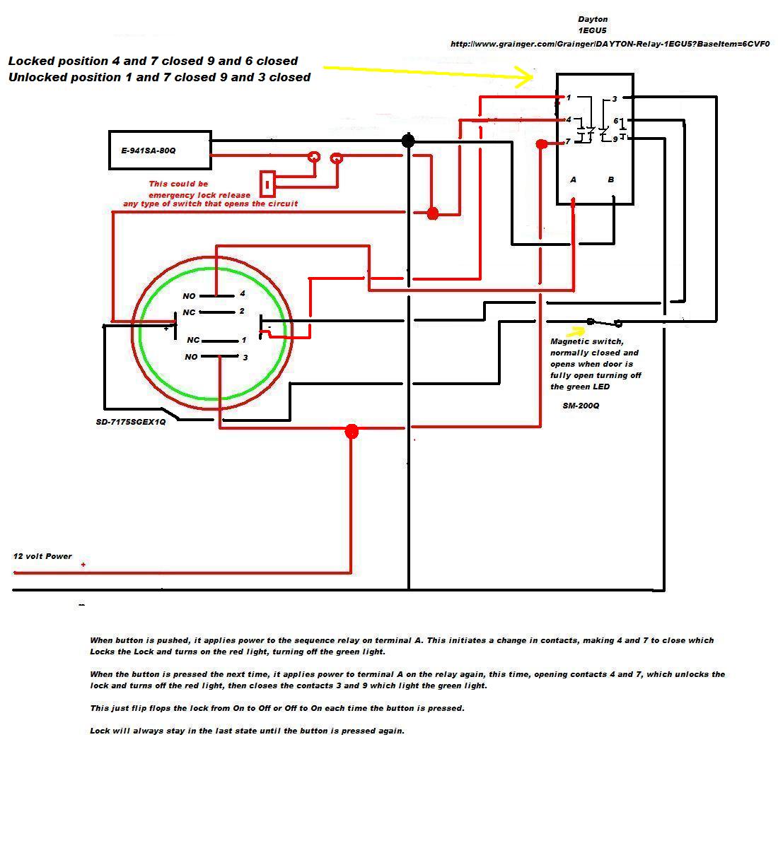
A 12V DC electromagnetic lock is designed with a push-to-lock and push-to-unlock mechanism using an existing LED indicator/switch. The switch should display a green light when unlocked and red when locked. The LED indicator/switch is the SD-7175SGEX1Q, which is...
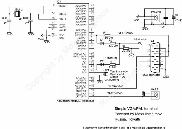
To prevent image distortion when receiving data via UART for VGA, it is advisable to conduct data exchange with the terminal approximately 300-600 microseconds after the vertical synchronization (VSYNC) signal. In a VGA system, the synchronization signals are crucial for...
This is a simple game circuit designed for multiplayer enjoyment. The objective is to score one hundred points within a limited timeframe. To restart the game, the S1 button switch must be pressed. It is important to ensure that...
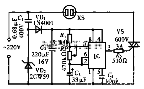
The circuit operates using an integrated circuit (IC) NE555 along with resistors R, RP, and capacitor C3, forming an astable multivibrator configuration. The output from pin 3 of the IC generates a square wave oscillation signal, which is passed...