
Music to light modulator circuit
SPECIFICATIONS
Input trigger voltage ............................2.3 - 2.5V (min)
AC input voltage..................................110V - 250V AC
Load (max) ..........................................500W @ 250V
220W @ 110V
WHAT TO DO IF IT DOES NOT WORK
First disconnect the board from the mains supply. Unplug it completely. Poor soldering is the most likely reason for the problem. Check all solder joints carefully under a good light. Next check that all components are in their correct position on the PCB. Is the optocoupler chip in the correct way? Is the potentiometer wound around too far? Reconnect the AC mains supply. Carefully use a voltmeter, follow around the tracks to check the potential differences at various parts of the circuit. Maybe the input signal is not enough to drive the optocoupler. It needs 1.2V and a current of 5mA (approx). A small tape recorder or radio will need an amplifier stage to amplify the signal before supplying it to the audio input. The light from the LED drives a phototriggered form of a silicon controlled rectifier (SCR) or triac. The LED and the triac are mounted within a single package. This triac is used as a driver to control a separate, slave triac capable of handling larger currents.
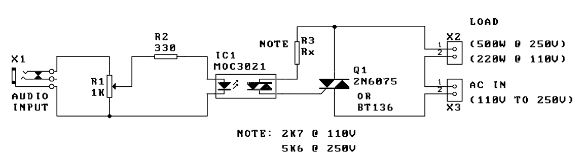
The music-to-light modulator circuit operates by translating audio signals into varying light intensity, creating a visually engaging experience synchronized with sound. The core of the circuit is the opto-triac (3021), which combines an LED and a triac in a single package, ensuring isolation between the high voltage AC circuit and the low voltage audio input. The LED within the opto-triac is driven by the audio signal, which is applied across its terminals.
A potentiometer is incorporated to adjust the sensitivity of the audio input, allowing for fine-tuning based on the characteristics of the audio source. Additionally, a resistor is included for protection against high signal peaks, preventing damage to the opto-triac from unexpected voltage spikes.
When the audio signal is present, the LED emits infrared light, which is detected by the internal triac driver. This driver activates a slave triac, which connects to the load (lighting system) and modulates its power based on the input audio intensity. The circuit is designed to handle significant loads, with specifications allowing for up to 500W at 250V AC and 220W at 110V AC.
In troubleshooting scenarios, if the circuit fails to operate, it is crucial to first disconnect it from the mains power supply. Common issues may include poor soldering or component misplacement on the PCB, which should be carefully inspected. The optocoupler must be verified for correct orientation, and the potentiometer should be checked for proper adjustment. Testing with a voltmeter can identify potential issues in the circuit, particularly ensuring that the input signal meets the required threshold of 1.2V and approximately 5mA to effectively drive the optocoupler. If necessary, an amplification stage may be required for weaker audio sources to ensure proper operation of the modulator.A music-to-light modulator is a circuit which controls the intensity of one or more lights in response to an audio input. The problem in older circuits is that there was a direct electrical connection between the lights using mains voltages (110 to 250V AC) and the amplifier circuit low 9 to 12 voltage levels.
Any fault in the high voltage circuit could completely destroy the low voltage section (and give a nasty shock to anyone holding it.) This potential problem has been overcome using the optocoupler. There is no electrical link between the two parts of the circuit. This kit introduces the opto-triac (3021) which is a further development of the optocoupler. An audio input controls a LED. The diagram shows how simple the circuit is. The audio signal is applied across the LED of the opto-triac. The potentiometer adjusts the input sensitivity while the resistor is used as protection from high signal peaks. The LED emits infra-red light in response to the input signal. The triac driver inside the 3021 package is sensitive to this IR light which activates a slave triac and load.
SPECIFICATIONS Input trigger voltage ............................2.3 - 2.5V (min) AC input voltage..................................110V - 250V AC Load (max) ..........................................500W @ 250V 220W @ 110V WHAT TO DO IF IT DOES NOT WORK First disconnect the board from the mains supply. Unplug it completely. Poor soldering is the most likely reason for the problem. Check all solder joints carefully under a good light. Next check that all components are in their correct position on the PCB. Is the optocoupler chip in the correct way? Is the potentiometer wound around too far? Reconnect the AC mains supply. Carefully use a voltmeter, follow around the tracks to check the potential differences at various parts of the circuit.
Maybe the input signal is not enough to drive the optocoupler. It needs 1.2V and a current of 5mA (approx). A small tape recorder or radio will need an amplifier stage to amplify the signal before supplying it to the audio input. The light from the LED drives a phototriggered form of a silicon controlled rectifier (SCR) or triac.
The LED and the triac are mounted within a single package. This triac is used as a driver to control a separate, slave triac capable of handling larger currents. 🔗 External reference
Related Circuits

The Mullard TCA240 is a dual balanced modulator-demodulator that effectively suppresses the carrier frequency at the output, which is essential for Single Sideband (SSB) or Double Sideband (DSB) operation in transmitters. The bias resistor R7 is adjustable to achieve...

This circuit utilizes the exceptionally low input current of 0.1 pA from the CA3420 BiMOS operational amplifier. It employs a single 10-MΩ resistor. The circuit operates within a range of ±50 pA, achieving a maximum full-scale sensitivity of ±1.5...
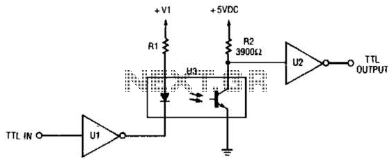
This circuit is a TTL-to-TTL isolator circuit. The driver circuit is an open-collector TTL inverter (U1). When the input is high, the output of the inverter is low. Thus, when the input is high, the output of U1 grounds...
An FM transmitter, commonly referred to as an FM transmitter, utilizes two transistors, specifically the 2N2222 model. When in operation, this FM transmitter requires a 9-volt battery for power and operates with an antenna that is less than 12...

The rectifier input is connected to the input, establishing a relationship where gain is inversely proportional to the input level. Consequently, a 20-dB reduction in input level results in a 20-dB increase in gain. The output is designed to...
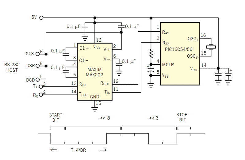
The popularity and easy access of RS-232 ports lend them to many communication projects. You can use a port as is or as a tiny parallel port when the exchange uses only control lines. Before the asynchronous serial-data transfer...