
5 to 30 Minute Timers
This circuit utilizes the CMOS 7555 timer, which is essential for achieving the desired timing functionality due to its lower power consumption and higher performance characteristics compared to the standard 555 timer. The choice of a Tantalum Bead capacitor for C1 is critical, as it ensures minimal leakage current, which is vital for maintaining accurate timing intervals in low-power applications.
The timing mechanism is controlled by a resistor network, with R1 playing a pivotal role in setting the timing period. The switch S3 allows for the selection of different resistor values, effectively altering the timing duration. In position "a," the circuit is configured with an 8.2 MΩ resistor, while position "f" increases the resistance to 49.2 MΩ, significantly extending the timing interval. This flexibility permits the user to tailor the timing characteristics to specific application requirements.
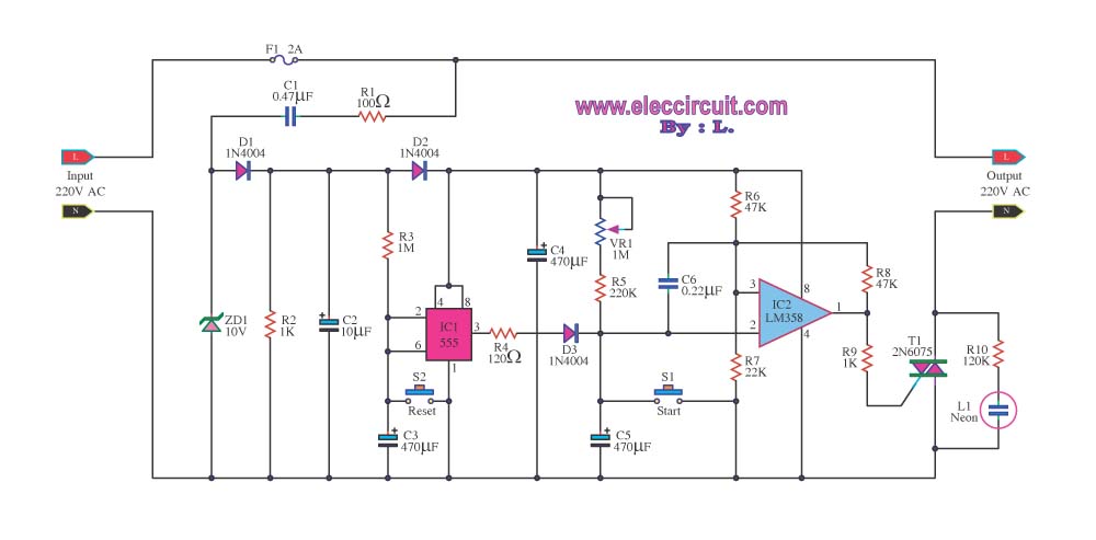
The output from Pin 3 of the 7555 timer is a square wave signal that can be used to control various devices. In this design, the output is fed into transistor Q1, which serves to amplify the output current. This amplification is crucial for driving a relay, allowing the circuit to control higher power loads that exceed the output capabilities of the timer alone. The relay acts as a switch, enabling or disabling connected devices based on the timing intervals set by the circuit.
Overall, this circuit exemplifies a practical application of the CMOS 7555 timer in timing and control systems, showcasing the importance of component selection and configuration in achieving reliable performance.Simple to build, simple to make, nothing too complicated here. However you must use the CMOS type 555 timer designated the 7555, a normal 555 timer will not work here due to the resistor values. Also a low leakage type capacitor must be used for C1, and I would strongly suggest a Tantalum Bead type.
Switch 3 adds an extra resistor in series to the timing chain with each rotation, the timing period us defined as :- Note that R1 has a value of 8. 2M with S3 at position "a" and 49. 2M at position "f". This equates to just short of 300 seconds for each position of S3. C1 and R1 through R6 may be changed for different timing periods. The output current from Pin 3 of the timer, is amplified by Q1 and used to drive a relay. 🔗 External reference
Related Circuits
The 555 adjustable timer circuit initiates timing upon activation. A green LED illuminates to indicate that the timing process is underway. Once the designated time period concludes, the... The 555 timer IC is a versatile device widely used in various...
This circuit was developed in response to requests from visitors of this website for a timer that can emit a beep after one, two, three minutes, and so on, for jogging purposes. As illustrated in the circuit diagram, SW1...
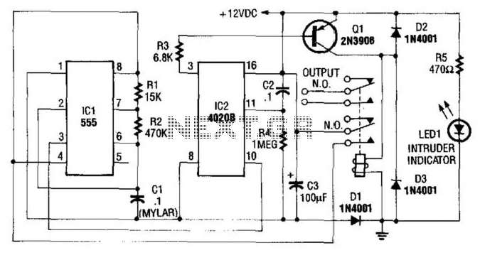
This circuit utilizes a NE555 timer and a CD4020B. When +12 Vdc is applied to the circuit, the output of IC2 is set low via C2, which activates the relay and IC1, functioning as a pulse generator. IC1 generates...
Most timer circuits are often used with electrical transformers operating at low voltages such as 9V and 12V, and they incorporate electrical control relays. The timer can be set for durations ranging from 1 to 15 minutes. Timer circuits are...
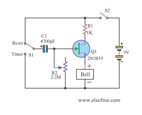
This circuit utilizes the FET 2N3819, which functions as a switch, operating in both conduction and non-conduction states. This behavior is in contrast to that of a bipolar transistor. The 2N3819 is a Junction Field Effect Transistor (JFET) known for...
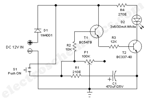
A well-designed circuit that automatically turns off if the pushbutton is held down or jammed for an extended period. It is not re-triggerable while the light remains on. The circuit initially starts at full brightness and gradually dims to...
Warning: include(partials/cookie-banner.php): Failed to open stream: Permission denied in /var/www/html/nextgr/view-circuit.php on line 713
Warning: include(): Failed opening 'partials/cookie-banner.php' for inclusion (include_path='.:/usr/share/php') in /var/www/html/nextgr/view-circuit.php on line 713