
timer control 1 15 minutes by triac 2n6075 and lm555 lm358
Timer circuits are essential components in various electronic applications, providing precise control over timing functions. These circuits typically consist of a timing element, which can be a resistor-capacitor (RC) network or a crystal oscillator, along with a control mechanism that dictates the operation of connected devices.
In the context of low-voltage transformers, such as those operating at 9V and 12V, timer circuits can effectively manage the operation of electrical control relays. This enables the automation of devices, ensuring they operate only during specified intervals. For instance, a timer circuit might be used to turn a light on for 10 minutes after detecting motion, providing convenience and energy efficiency.
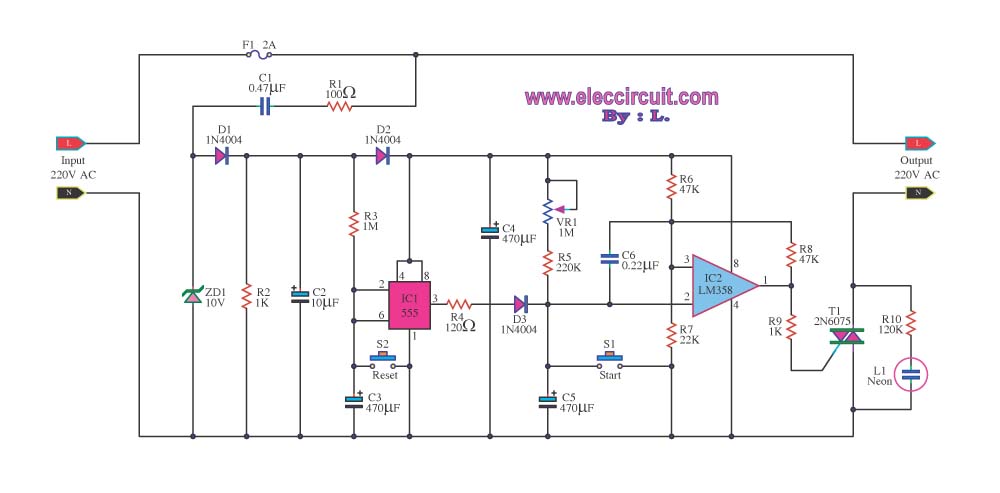
The implementation of a 1-15 minute timer can be achieved using a 555 timer IC configured in monostable mode. In this configuration, the timer generates a single pulse of a specified duration when triggered. The duration can be adjusted by selecting appropriate resistor and capacitor values. For example, using a potentiometer in conjunction with a capacitor allows for variable timing settings, enabling users to customize the timing range easily.
The output of the timer circuit can be used to drive a relay that controls higher voltage loads, ensuring that the low-voltage timer circuit remains safe and functional. When the timer elapses, the relay can switch on or off connected devices, providing seamless control over electrical appliances.
In summary, timer circuits utilized with low-voltage transformers and control relays offer versatile solutions for time-dependent applications, enhancing both functionality and efficiency in electronic systems.Most timer circuits. Often used with electrical transformers containing low as 9V and 12V, and use of electrical control relays.but the 1-15 minute timer.. 🔗 External reference
Related Circuits
The circuit shown above can be used to control a unipolar stepper motor which has FOUR coils. The above circuit can be for a motor current of up to about 500mA per winding with suitable heat sinks for the...
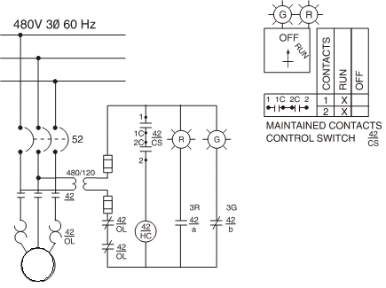
Motor starters generally fall into two categories: full-voltage or reduced-voltage. The choice of which type of starter to use depends on various factors, such as the current-carrying capacity of plant wiring, the ability of plant power supplies to absorb...
The TRIAC is a three-terminal device that operates similarly to the SCR. Unlike the SCR, which conducts current flow during only one alternation of an AC cycle, the TRIAC allows current to flow during both alternations. The schematic symbols...
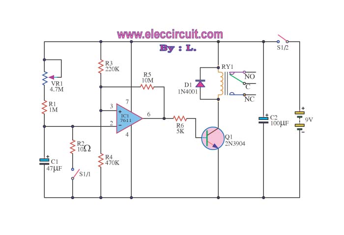
When switch S1/2 is activated, it powers the circuit C1, which utilizes the UA741 operational amplifier for voltage comparison. Pin 3 serves as the non-inverting input, while pin 2 is the inverting input. The voltage at pin 3 is...
Figure 2-32 (a) illustrates the time control diagram for a motor operated by switch S1. When S1 is set to position 1, the power driver circuit supplies current to the motor, enabling it to run. When S1 is switched...
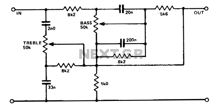
A simple circuit using two potentiometers and easily available standard value components provides tone control. The impedance level is suitable for low-level transistor or op-amp circuitry. This tone control circuit typically employs two potentiometers to adjust the bass and treble...