
Audio Odd Block KT88 Series 1 Tube Amp-Power Supply
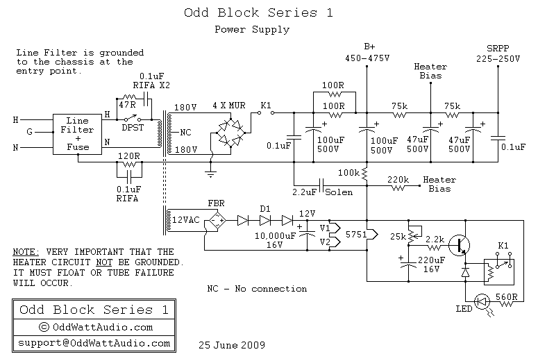
The schematic presents a detailed layout for the ability accumulation system, which is integral to the overall amplifier design. The IEC inlet serves as the primary entry point for mains voltage, ensuring safety and compliance with electrical standards. The inclusion of a 3 Ampere fuse provides overcurrent protection, while the EMI filter mitigates electromagnetic interference, enhancing the performance and reliability of the amplifier.
The power transformer plays a critical role in voltage conversion, delivering the specified dual high-voltage outputs of 180V and a low-voltage output of 12V. The use of an OEM transformer from Edcor ensures that the design meets the necessary specifications for optimal performance. The power supply capacitors, selected for their high voltage rating and reliability, are crucial for filtering and stabilizing the DC voltage supplied to the amplifier's circuitry.
The Vishay/Dale wire wound resistors are chosen for their ability to handle high power dissipation, ensuring stability during operation. Carbon film resistors are utilized in lower power applications, providing accuracy and low noise characteristics. The rectification of the High-Tension supply is achieved through the STTH5 ultrafast rectifiers, which facilitate rapid switching and minimize voltage drop, thus improving overall efficiency.
CRC filtering is employed to smooth out the rectified voltage, reducing ripple and providing a stable DC output. The 12V DC supply for tube heaters is essential for maintaining the required operating temperature of the tubes, contributing to the amplifier's performance. The adjustable delay circuit is a valuable feature that protects the amplifier’s components during power-up, allowing the system to stabilize before applying high voltage to the tubes, thereby prolonging their lifespan and enhancing reliability.
In summary, the schematic provides a comprehensive overview of the ability accumulation system, integrating various components that work together to deliver reliable and efficient performance in the amplifier design.A schematic of the ability accumulation is apparent below. Like the amplifier schematic, the ability accumulation ambit is © OddWatt Audio and permission to host the schematic on this armpit has been provided by OddWatt Audio. You are chargeless to use the schematic for personal, non-commercial use. Mains ability enters the amplifier through an I EC atrium amid at the rear of the amp. The IEC atrium includes a 3 Ampere agglutinate and an EMI filter. The ability agent is an OEM bogus by Edcor with ratings of 180V-0-180V at 250 mA and 12V at 4A. Ability accumulation capacitors are Panasonic ECG alternation 500 volt electrolytic and Solen Polypropyene. The ample ability resistors are Vishay/Dale wire anguish and the actual resistors are carbon film. The High-Tension (HT) accumulation is rectified with STTH5 ultrafast aerial voltage rectifiers and uses CRC filtering.
A 12V DC accumulation is acclimated for the tube heaters. An adjustable adjournment ambit is acclimated to adjournment the HT accumulation on ability up. 🔗 External reference
Related Circuits
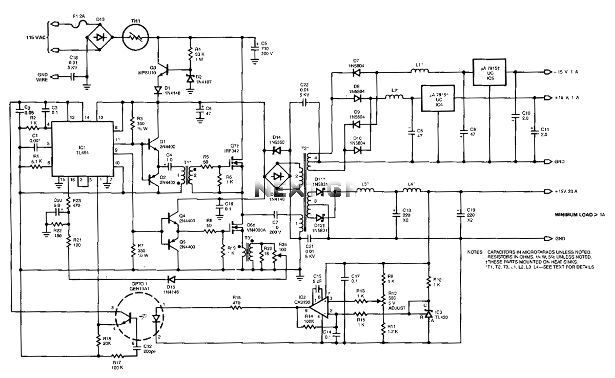
The power supply employs two VN4000A 400-V MOSPOWER FETs configured in a half-bridge arrangement. It provides outputs of +5 V at 20 A and ±15 V (or ±12 V) at 1 A. The low-current outputs utilize linear three-terminal regulators,...
The amplifier of circuit uses negative current feedback. The load current depends mainly on the input signal and not so much on the impedance of the loudspeaker. The inductor current of the loudspeaker develops a voltage across R7. This...
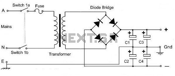
This is a basic dual polarity power supply circuit diagram. It requires the following components: a center-tapped transformer, four diode rectifiers (or one diode bridge), and four electrolytic capacitors. The value of each component is essential for the circuit's...
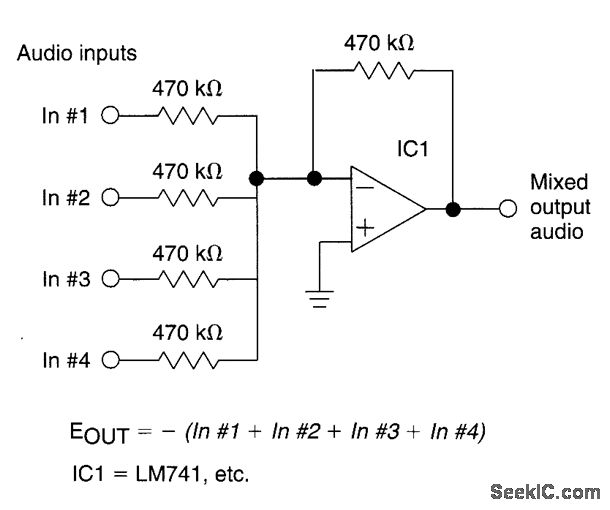
The circuit features four inputs. The voltage gain between each input and the output is maintained at unity by the relative values of the 470kΩ input resistor and the 470kΩ feedback resistor. The described circuit operates as a voltage buffer...
In previous Instructables tutorials, equipment used for DNA electrophoresis and imaging has been described. This includes a mini-gel electrophoresis apparatus. The mini-gel electrophoresis apparatus is designed for the separation of nucleic acids such as DNA and RNA. The core components...
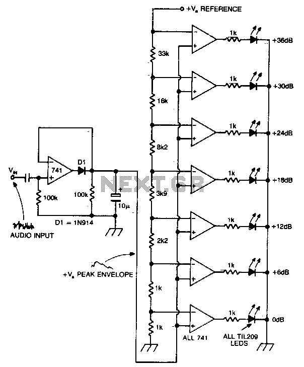
A vertical column of LEDs is configured so that as the audio signal level rises, an increasing number of LEDs illuminate. The LEDs are arranged in increments of 6 dB. The circuit features a fast response time and a...