
how to make inexpensive current
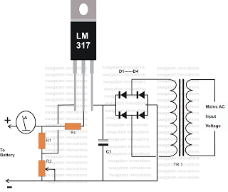
The described circuit utilizes the LM317 voltage regulator, a versatile integrated circuit widely used for providing a stable output voltage. In this application, it is configured as a constant current source to safely charge a 12-volt lead-acid battery. The LM317 requires a minimum input-output voltage differential to function correctly, typically around 3 volts. Therefore, the transformer bridge power supply should be selected to provide an adequate input voltage above 15 volts to ensure proper regulation.
Resistor R1 is a fixed resistor that sets a baseline for the output voltage, while variable resistor R2 allows for fine-tuning of the output voltage to match the battery's requirements. The adjustment of R2 directly influences the charging voltage applied to the battery, which is crucial for optimizing the charge cycle and preventing overcharging. The current flowing through the battery is monitored using an ammeter, which provides real-time feedback on the charging status.
The LM317 features built-in current limiting capabilities. When the charging current approaches a predefined threshold, the IC automatically reduces the output voltage to prevent excessive current flow, thereby protecting the battery from potential damage. This feedback mechanism is vital for maintaining battery health and prolonging its operational life.
In summary, this charging circuit is designed to provide a reliable and adjustable method for charging 12-volt lead-acid batteries. By employing the LM317 in conjunction with a transformer bridge power supply, accurate voltage regulation and current limiting can be achieved, ensuring safe and efficient battery charging. The inclusion of an ammeter further enhances the system by allowing users to monitor the charging process effectively.Charging any type of chargeable battery can be critical and involves some attention to be paid. Especially the current or the rate at which the battery is being charged becomes an important factor as far as maintaining life and efficiency of the battery for a longer period of time is concerned. The circuit diagram presented here shows how the IC L M317 ca be configured using just a couple resistors and an ordinary transformer bridge power supply for charging a 12 volt lead acid battery with utmost accuracy. The ADJ pin of the IC is fixed to the junction of the resistor R1 and the variable resistor R2. R2 can be fine set for aligning the final output voltage with the battery. As long as this current is within the desired safe range, the voltage remains at the specified level, however if the current tends to rise, the voltage is withdrawn by the IC and dropped, restricting the current rise any further and ensuring appropriate safety for the battery.
The connected ammeter is used for monitoring the charge condition of the battery. Once theammetershows zero voltage, the battery may bedetachedfrom the charger for the intended use. 🔗 External reference
Related Circuits
A simple method for charging a battery from a higher voltage battery is illustrated in the circuit below on the left. Only one resistor is required to establish the desired charging current, which is determined by dividing the difference...
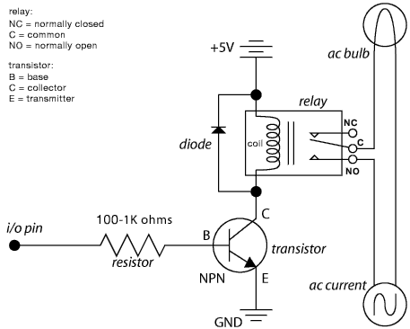
The schematic illustrates the Relay Wiring Circuit Diagram used to control an air conditioner or other high-current devices via a microcontroller. The relay wiring circuit serves as an interface between low-voltage microcontroller signals and high-voltage appliances, such as air conditioners....
An operational amplifier circuit can provide a constant voltage source with a high amplification factor and substantial load current. Even with significant variations in circuit parameters, the output voltage maintains high precision. The output current limit is managed by...
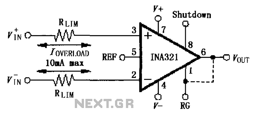
The input current protection circuit for the INA321/322 is illustrated. The INA321/322 features input terminal electrostatic discharge (ESD) protection diodes that become conductive when the input voltage exceeds the supply voltage by 500mV. The protection diodes will conduct, and...
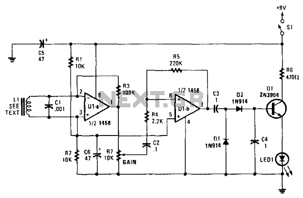
This circuit utilizes a dual operational amplifier to drive a rectifier and emitter-follower configuration, which indicates AC current on an LED. The inductor L1 is formed by a winding of a audio transformer, created with a pick-up coil consisting...
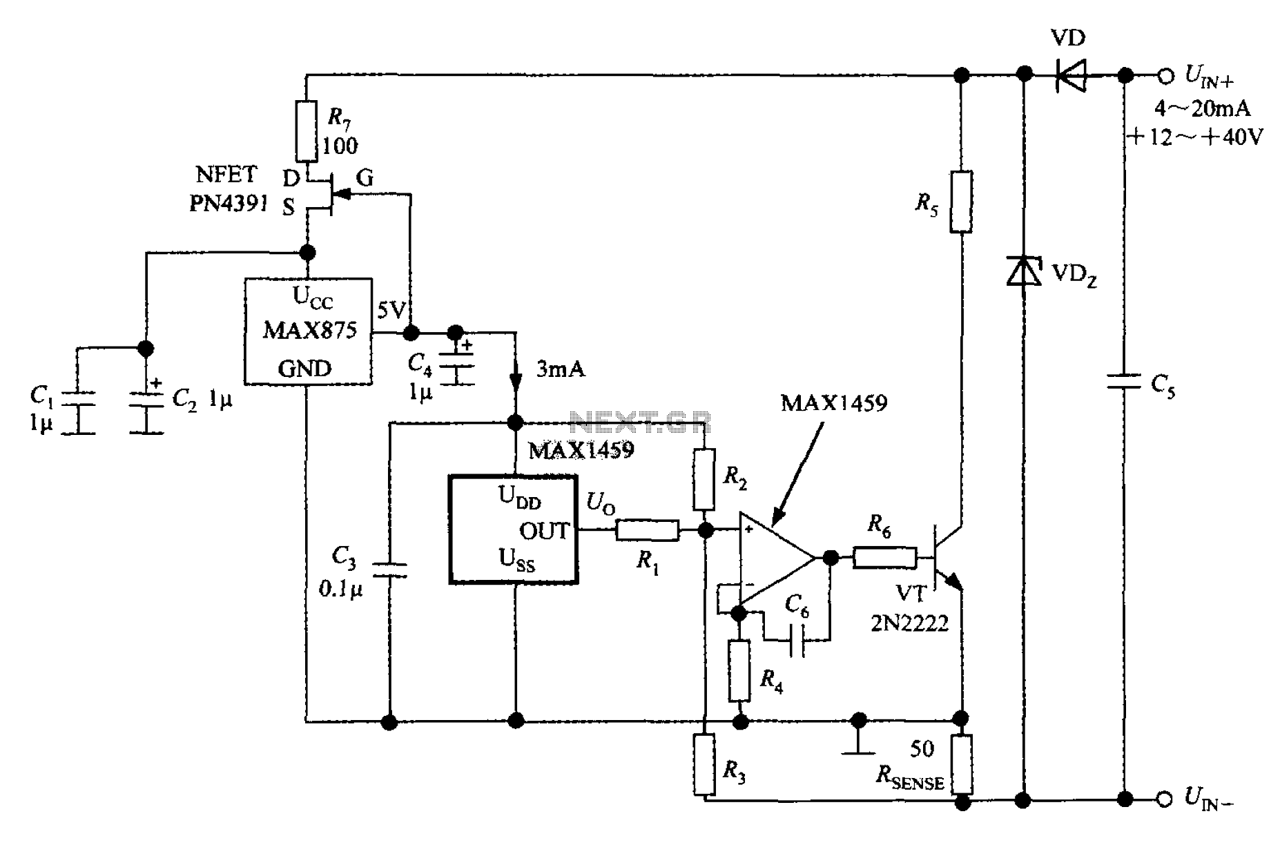
A 4 to 20 mA current transmitter circuit is implemented using the MAX1459, as illustrated in the accompanying figure. The output voltage from the programmable gain amplifier (PGA) is supplied to a spare amplifier chip, and subsequently, an external...