
5 Volt to 12 Volt bi-directional lamp sequencer

The circuit utilizes a bi-directional lamp sequencer designed to control multiple 12-volt, 25-watt lamps. The core of the control mechanism is a 74HCT138 decoder, which serves to decode input signals and activate the corresponding output lines. To handle the increased current demands of the lamps, two additional transistors are employed to amplify the output from the decoder.
A 6.8-volt, 1-watt zener diode is strategically placed in series with the ground connections of all CMOS integrated circuits, specifically the 74HC14, CD4516, and 74HC138. This configuration ensures that the total voltage supplied to the CMOS devices is regulated to approximately 5.2 volts. Consequently, the output voltage from the decoder is reduced from +12 volts to around +7 volts when activated, allowing for proper operation of the subsequent transistor stages.
The first amplification stage consists of a 2N2905 PNP transistor configured as an emitter follower. This configuration provides a high input impedance, which is crucial for interfacing with the decoder output. The emitter follower supplies approximately 80 mA of current to the base of the subsequent 2N3055 NPN power transistor. The 2N3055 is responsible for driving the 12-volt lamps, capable of supplying 2 amps or more, thus ensuring adequate brightness and performance.
The voltage drop across the 2N2905 when conducting is approximately 7 volts, resulting in a heat dissipation of about 0.6 watts. Under normal operation, this level of heat generation is manageable, and a heat sink is generally not required, especially when multiple lamps are sequenced. However, if the circuit remains idle with a single output active, the PNP transistor may become quite warm.
The 2N3055 operates as a power switch, characterized by a low voltage drop (less than 0.5 volts) during conduction. This efficiency further negates the need for a heat sink under typical conditions. For flexibility in design, alternative transistors can be utilized, such as the TIP29 or TIP31 in place of the 2N3055, while any medium power PNP transistor rated for 500 mA can serve as a suitable substitute for the 2N2905. This versatility allows for adaptability in various applications while maintaining the performance integrity of the circuit.The circuit below is designed to be used with the bi-directional lamp sequencer shown above on this same page. Two additional transistors are used to increase the current from the 74HCT138 decoder to control 12 volt 25 watt lamps.
A 6.8 volt/1 watt zener diode is used in series with the ground connection of all the CMOS ICs (74HC14, CD4516 and 74HC138s) so that the total voltage across the CMOS devices will be about 5.2 volts and the outputs will move from +12 to about +7 when selected. The 2N2905/PNP transistor stage is connected as an emitter follower which provides a high impedance to the decoder output and supplies about 80 mA of current to the base of the 2N3055 NPN power transistor which then supplies 2 or more amps to the 12 volt lamp. The voltage across the PNP transistor will be about 7 volts when it is turned on and the heat dissapation will be about 0.6 watts.
That should't require a heat sink if several lamps are sequencing but it may get quite warm if the circuit is idle on a single output. The 2N3055 power transistor operates as a switch and drops very little voltage (less than 0.5) when conducting, and will not require a heat sink.
Other transistors may be substituted such as the TIP29 or TIP31 for the 2N3055 and most any medium power (500mA) PNP for the 2N2905. 🔗 External reference
Related Circuits
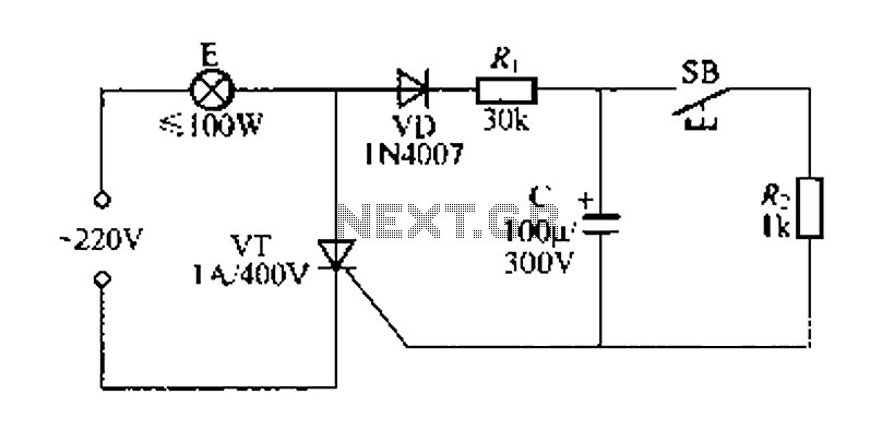
Figure 57 illustrates a simple delay lamp circuit that connects to lamp E using a two-wire connection. This design allows for the security bars to be installed directly, enabling replacement with a standard wall switch without altering the existing...
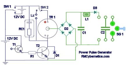
The diagram illustrates a series connection of cell diode capacitors, each rated for an increasing voltage of 300 V. This configuration generates a high DC voltage supply of 40 kV, which can be utilized for various experimental applications. With...

An expanded scale voltmeter (ESV) can be crucial for aircraft operation. This assertion is based on the dependency of the radio link, which allows control of the aircraft, on nickel-cadmium (NiCd) batteries located in both the transmitter and receiver....

A simple 5-volt switching power supply electronic circuit project can be designed using the FAN302HL, a highly integrated PWM controller integrated circuit. This IC provides several features that enhance the performance of general flyback converters. The constant-current control of...
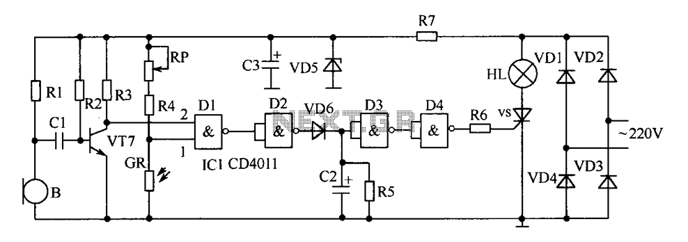
The delay-saving lamp circuit functions as a sound and light control delay energy-saving lighting system. It can directly replace a standard light switch without modifying the existing lighting circuits. In bright or daytime conditions, the sound control feature ensures...
The Analog Devices ACP3610 is a voltage doubler that operates using a switched-capacitor converter based on the push-pull principle. The output switching frequency is approximately 550 kHz. The push-pull configuration involves two charge pumps that function in parallel but...