
high voltage circuits
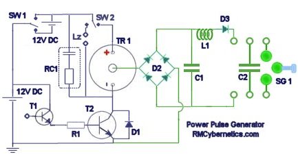
The circuit design consists of multiple stages of capacitors and diodes arranged to form a voltage multiplier. The initial stage begins with a standard 12 V power supply, which is fed into the first capacitor and diode pair. Each capacitor is charged to the input voltage, while the diode prevents reverse current flow, allowing the capacitor to hold its charge. As the voltage progresses through each subsequent stage, the capacitors charge to higher voltages, effectively multiplying the input voltage.
In this configuration, each capacitor is rated for 300 V, ensuring that the components can handle the increasing voltage levels without failure. The use of four doubler stages enables the final output to reach 160 kV, suitable for high-energy experiments. The circuit's design must be carefully considered to ensure that all components are rated for the maximum expected voltage and that proper insulation and spacing are maintained to prevent arcing.
The high voltage DC power supply produced by this circuit is particularly useful for applications in scientific research, where it can be utilized to power devices such as electron tubes and x-ray tubes, which require stable and high voltage inputs. Furthermore, the capability to drive Tesla coils and other high-power coils makes this power supply versatile for various experimental setups, including demonstrations of electrical phenomena and high-voltage experiments.
Safety precautions are paramount when working with high voltage systems. It is essential to incorporate proper enclosures, use insulated tools, and ensure that all components are securely mounted to prevent accidental contact. Additionally, adequate grounding and discharge mechanisms should be implemented to mitigate the risks associated with high voltage operation.The diagram shows a set of cell diode capacitor connected in series, each set of increasing voltage 300 V. This Supply generates DC high voltage 40kV, with which you can make interesting experiments. With the available 40 kV capacitors, 160 kV output voltage could only be obtained with four doubler stages.
Estimated voltage output is 9kV from 12V supply. High voltage DC power supplies are used by science enthusiasts for powering electron tubes and x-ray tubes. A Multipurpose power pulse generator capable of driving Tesla Coils and other high power coils. 🔗 External reference
Related Circuits
The hobby circuit described utilizes a unique method to generate approximately 12,000 volts with a current of about 5 microamperes. It employs two silicon-controlled rectifiers (SCRs) that form two pulse generator circuits. These SCRs discharge a 0.047 microfarad, 400-volt...
The circuit depicted in the figure is designed for multi-temperature testing, allowing for the switching of the thermocouple corresponding to the active channel. At the core of this design is a 555 timer configured in a monostable delay mode....
Advanced power control systems utilize electronic components such as thyristors for power switching, motor control, and other applications. These systems are involved in inverter design, lamp dimming, and speed control of motors. Triacs are the most commonly used semiconductor...
Designing a wide-range variable power supply using a linear regulator is straightforward; however, it suffers from poor efficiency when regulating a constant 60-volt source. A wide-range variable power supply can be implemented using a linear regulator, which allows for adjustable...
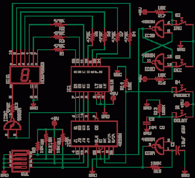
The CD4538 is a dual Monostable Multivibrator. When triggered, the chip generates a single pulse or a high-low event. The T+ pin (pin 4) of U1a serves as the positive edge trigger input, while the T- pin (pin 5)...
555 timer circuits LM555 - Astable Oscillator Calculator, Capacitor Calculator, Basic Circuits for the LM555 Timer, Triggering and Timing Helpers for Monostable Timers, Controlling Circuits for LM555 Timers, Advanced Circuits for the LM555 Timer, LM556 Timers with Complementary or...
Warning: include(partials/cookie-banner.php): Failed to open stream: Permission denied in /var/www/html/nextgr/view-circuit.php on line 713
Warning: include(): Failed opening 'partials/cookie-banner.php' for inclusion (include_path='.:/usr/share/php') in /var/www/html/nextgr/view-circuit.php on line 713