
5 Zone Alarm System
The alarm system is designed to provide comprehensive security for small spaces by utilizing a combination of zones that allow for both immediate and delayed response to unauthorized access. The use of CMOS technology ensures low power consumption and high reliability. The system's architecture allows for easy installation and customization, accommodating various switch types and configurations based on user preferences and specific site requirements.
The timed entry/exit zone (Zone 1) is critical for allowing authorized users to enter and exit without triggering the alarm, while the immediate zones (Zones 2-5) are strategically placed to ensure rapid response to any unauthorized entry. The inclusion of RF immunity through capacitors helps mitigate interference from external sources, ensuring the system's reliability over longer wiring distances.
The key switch not only serves as the primary control for arming and disarming the system but also enhances security by requiring a physical key for operation. The exit delay, adjustable through the timing components, allows users to exit the premises without the alarm activating prematurely.
LED indicators provide clear visual feedback regarding the system's status, ensuring that users are aware of whether the system is armed or disarmed. The re-entry switch, designed to be discreet, allows users to enter the premises without triggering the alarm, maintaining security while providing convenience.
The panic button feature is an essential component for emergency situations, allowing users to quickly trigger the alarm in case of a threat. The relay contacts are critical for controlling the alarm output, with RLA1 maintaining the alarm state and RLA2 activating the audible alarm, such as a siren or buzzer, to alert occupants and deter intruders.
Overall, this alarm system's design emphasizes user-friendly operation, adaptability to various environments, and robust security features, making it a suitable choice for residential and small commercial applications.This is a complete alarm system with 5 independent zones suitable for a small office or home environment. It uses just 3 CMOS IC`s and features a timed entry / exit zone, 4 immediate zones and a panic button.
There are indicators for each zone a "system armed" indicator. The schematic is as follows: Each zone uses a normally closed contact. These can be micro switches or standard alarm contacts (usually reed switches). Suitable switches can be bought from alarm shops and concealed in door frames, or window ledges. Zone 1 is a timed zone which must be used as the entry and exit point of the building. Zones 2 - 5 are immediate zones, which will trigger the alarm with no delay. Some RF immunity is provided for long wiring runs by the input capacitors, C1-C5. C7 and R14 also form a transient suppressor. The key switch acts as the Set/Unset and Reset switch. For good security this should be the metal type with a key. At switch on, C6 will charge via R11, this acts as the exit delay and is set to around 30 seconds. This can be altered by varying either C6 or R11. Once the timing period has elapsed, LED6 will light, meaning the system is armed. LED6 may be mounted externally (at the bell box for example) and provides visual indication that the system has set. Once set any contact that opens will trigger the alarm, including Zone 1. To prevent triggering the alarm on entry to the building, the concealed re-entry switch must be operated.
This will discharge C6 and start the entry timer. The re-entry switch could be a concealed reed switch, located anywhere in a door frame, but invisible to the eye. The panic switch, when pressed, will trigger the alarm when set. Relay contacts RLA1 provide the latch, RLA2 operate the siren or buzzer. 🔗 External reference
Related Circuits
This circuit alerts users when the AC mains supply fails by sounding an alarm and providing a backup light to aid in locating a torch or generator key in the dark. It is powered directly by a 9V PP3/6F22...
The primary components of this doorbell circuit include two NE555 timer integrated circuits (ICs). When the switch S1 is pressed momentarily, the loudspeaker emits a bell tone for the duration determined by the time period of the monostable multivibrator...

A calculating resonance capacity is derived from formula (1), and an NFC Tag LSI is integrated into the antenna circuit board. The resonance frequency is measured, followed by adjustments to the resonance capacity. The circuit design involves calculating the resonance...

An LM2808 performs IF amplification of the 4.5-MHz sound subcarrier, limiting, detection, and audio amplification. If the center frequency must be changed, then change L1/C4. Audio output is 0.5 W. R3 is the volume control. The LM2808 is an integrated...
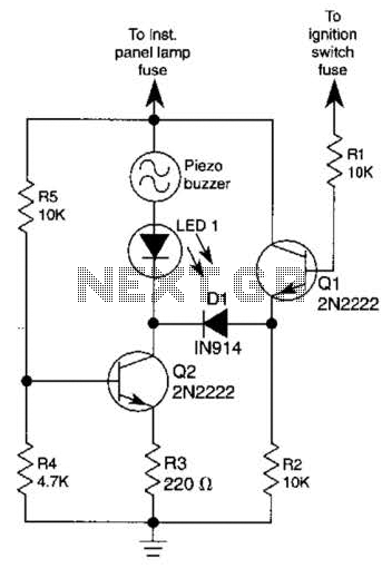
The base of Q1 is connected to the car's ignition circuit; the easiest point to make that connection is at the ignition switch fuse in the car's fuse panel. Also, one side of the piezoelectric buzzer is connected to...

The circuit schematic presented in Figure 1 consists of an SCR, R1, and an AN SCR trigger switch circuit, along with an analog circuit composed of IC1, R2, VT1, VT2, and a BL siren. Typically, the circuit is designed...