
Normally closed contact burglar alarm circuit diagram
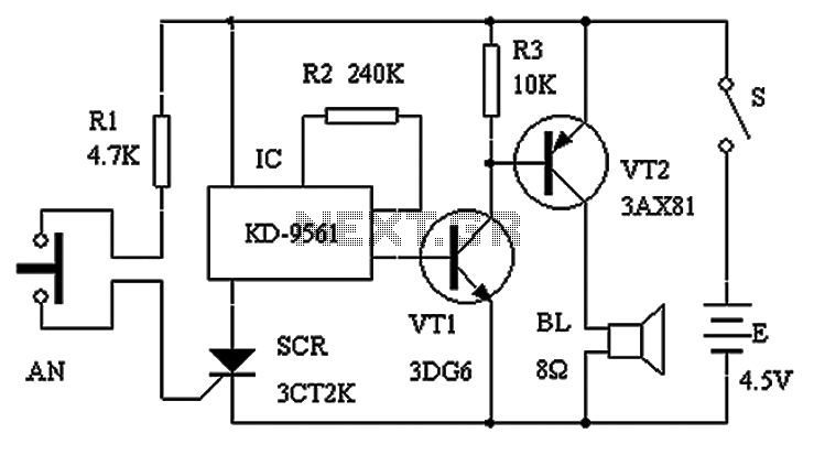
The circuit operates as a security system for household appliances, utilizing a silicon-controlled rectifier (SCR) as a key component for triggering the alarm. The SCR is controlled by a resistive divider formed by R1, which ensures that when the circuit is activated, sufficient voltage is present to switch the SCR into conduction mode. The use of normally closed contacts in the system creates a fail-safe mechanism, as any tampering with the appliances will trigger the alarm.
In the event of an unauthorized removal of the appliance, the circuit detects the change in state of the contacts, which leads to a change in the voltage across R1. This change triggers the SCR, allowing current to flow through it and powering IC1, which is likely a timer or oscillator circuit that drives the output stage. The output stage, composed of transistors VT1 and VT2, functions as an amplifier to drive the BL siren, producing a loud alarm sound that serves as a deterrent against theft or tampering.
The design ensures that once triggered, the alarm remains active regardless of the state of the appliance or the contacts, which adds an additional layer of security. Disarming the system requires physical access to the alarm control panel, which is intended to prevent unauthorized individuals from easily disabling the alarm. This setup is particularly useful in scenarios where the protection of valuable household appliances is critical, providing peace of mind to the owner. Circuit schematic shown in Figure 1.SCR, R1 and AN SCR trigger switch circuit composed; IC1, R2, VT1, VT2 and BL siren composed of analog circuits. Usually, AN oppression by ho usehold appliances, making two normally closed contacts disconnect, SCR trigger signal without blocking, the alarm does not work. When home appliances were lifting, AN two contacts automatically closed, the trigger terminal SCR trigger signal via R1 obtained from the positive power supply, SCR conduction, IC1 power of work, output terminal siren signal by VT1, VT2 power zoom, push speaker loud alarm sound.
In this case, even if the appliance back in place or destroy AN, can not stop the alarm sound. Only the owner to open the alarm installation and other people together and sometimes difficult to find the switch S, in order to disarm the alarm.
Related Circuits
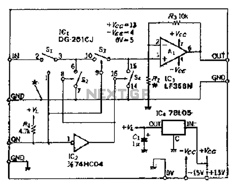
Analog switches SL and SA disconnect the inverted logic signal to terminal 2. S1 and S4 are turned on, allowing capacitance between S1 and S8 to couple. S2 and S4 shunt with an on-state resistance ranging from 50 to...
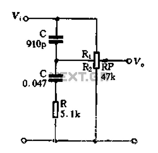
Figure 1-89 illustrates a loudness control circuit. A potentiometer is connected to ground, with 30% of the total resistance at the tap. When the slider arm is adjusted to the tap position, a midrange attenuation of 30 dB is...
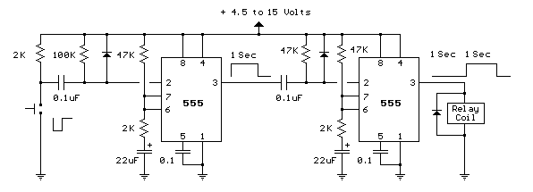
This toggle circuit utilizes two 555 timers configured as inverters. Pins 2 and 6 serve as the threshold and trigger inputs for the first timer, while pin 5 provides the output. The output at pin 5 will consistently reflect...
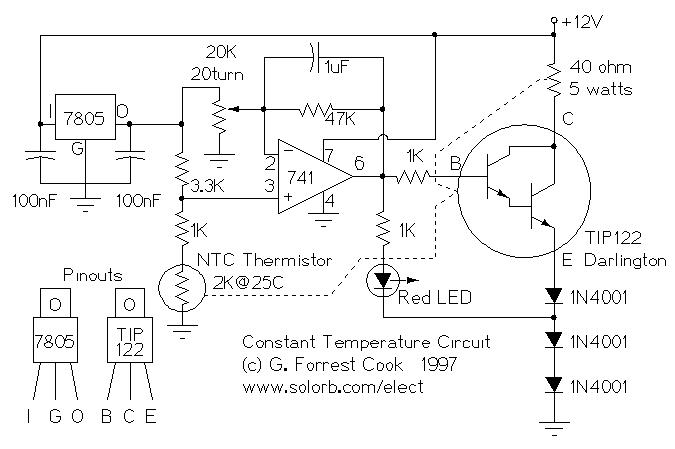
Constant Temperature Circuit. G. Forrest Cook 1997. Introduction: This circuit is a generic low-power temperature controller that can be used for stabilizing temperature. The constant temperature circuit described is designed to maintain a stable temperature in various applications, utilizing low...
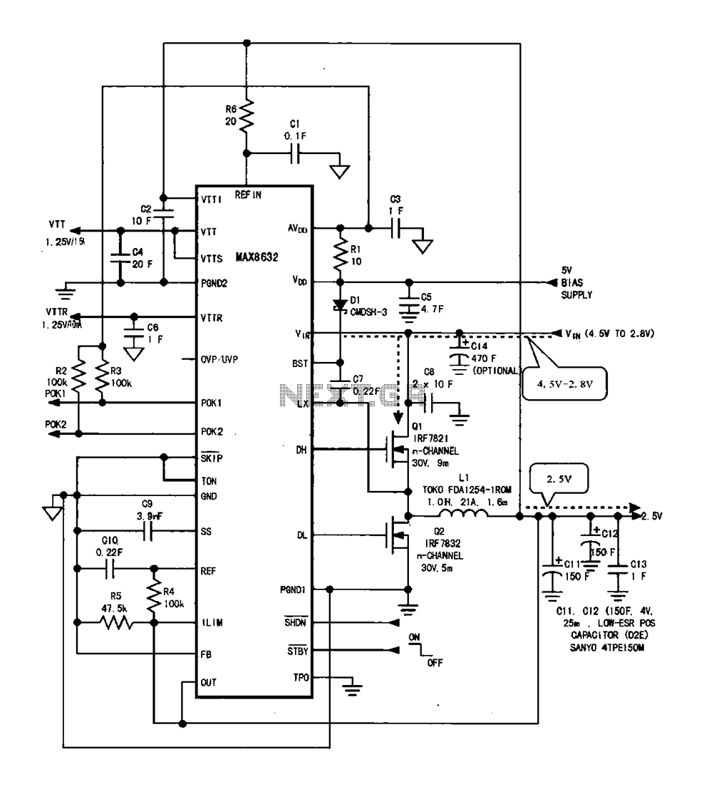
DDR memory power supply circuit. This circuit illustrates the power supply configuration for notebook DDR memory, utilizing the MAX8632 power control circuit chip. The power supply terminal VDD is connected to the voltage detection point 1. The battery DC...
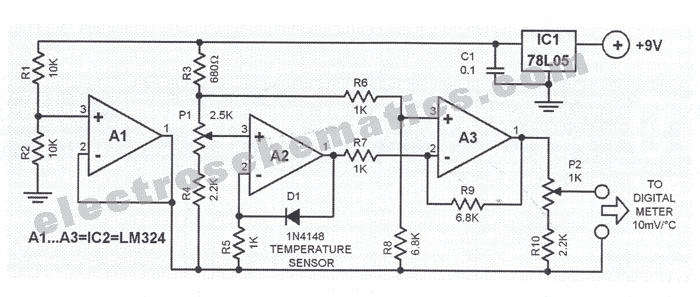
The circuit presented is designed to prevent burning one's tongue by monitoring the temperature of coffee. It consists of a voltage regulator, a temperature-to-voltage converter, a comparator, and two LEDs. In general, the circuit operates as follows: if the...
Warning: include(partials/cookie-banner.php): Failed to open stream: Permission denied in /var/www/html/nextgr/view-circuit.php on line 713
Warning: include(): Failed opening 'partials/cookie-banner.php' for inclusion (include_path='.:/usr/share/php') in /var/www/html/nextgr/view-circuit.php on line 713