
Mains Supply Failure Alarm
The circuit operates as a reliable alert system for power outages, combining alarm and illumination functionalities for user convenience. The use of a compact 9V battery ensures portability and ease of use. The optocoupler IC MCT2E plays a crucial role in detecting the presence of AC mains voltage, ensuring that the circuit is only active when necessary. The design incorporates safety features such as the use of a bridge rectifier to manage AC input, converting it to a usable DC signal for the rest of the circuit.
The monostable multivibrator IC CD4538 is utilized effectively to create a time delay for the alarm and light activation, allowing users ample time to respond to the power failure. The adjustable timeout period provides flexibility, enabling customization based on user needs. The inclusion of a piezo buzzer ensures that the alarm is audible even in low-light conditions, while the white LED serves as a practical solution for locating essential items in the dark.
Overall, this circuit exemplifies a well-thought-out design that addresses the critical need for alerts and illumination during power outages, enhancing safety and convenience for users.Whenever AC mains supply fails, this circuit alerts you by sounding an alarm. It also provides a backup light to help you find your way to the torch or the generator key in the dark. The circuit is powered directly by a 9V PP3/6F22 compact battery. Pressing of switch S1 provides the 9V power supply to the circuit. A red LED (LED2), in conjunctio n with zener diode ZD1 (6V), is used to indicate the battery power level. Resistor R9 limits the operating current (and hence the brightness) of LED2. When the battery voltage is 9V, LED2 glows with full intensity. As the battery voltage goes below 8V, the intensity of LED2 decreases and it glows very dimly. LED2 goes off when the battery voltage goes below 7. 5V. Initially, in standby state, both the LEDs are off and the buzzer does not sound. The 230V AC mains is directly fed to mains-voltage detection optocoupler IC MCT2E (IC1) via resistors R1, R2 and R3, bridge rectifier BR1 and capacitor C1. Illumination of the LED inside optocoupler IC1 activates its internal phototransistor and clock input pin 12 of IC2 (connected to 9V via N/C contact of relay RL1) is pulled low.
Note that only one monostable of dual-monostable multivibrator IC CD4538 (IC2) is used here. When mains goes off, IC2 is triggered after a short duration determined by components C1, R4 and C3. Output pin 10 of IC2 goes high to forward bias relay driver transistor T1 via resistor R7. Relay RL1 energises to activate the piezo buzzer via its N/O contact for the time-out period of the monostable multivibrator (approximately 17 minutes). At the same time, the N/C contact removes the positive supply to resistor R4. The time-out period of the monostable multivibrator is determined by R5 and C2. Simultaneously, output pin 9 of IC2 goes low and pnp transistor T2 gets forward biased to light up the white LED (LED1).
Light provided by this back-up LED is sufficient to search the torch or generator key. During the mono time-out period, the circuit can be switched off by opening switch S1. The on` period of the monostable multivibrator may be changed by changing the value of resistor R5 or capacitor C2. If mains doesn`t resume when the on` period of the monostable lapses, the timer is retriggered after a short delay determined by resistor R4 and C3.
🔗 External reference
Related Circuits
The circuit diagram for a multiple output digital camera power supply using the MAX1802 is illustrated below. The MAX1802 chip features two buck converters and three boost converters. It accepts an input voltage range of 2.5 to 11V and...
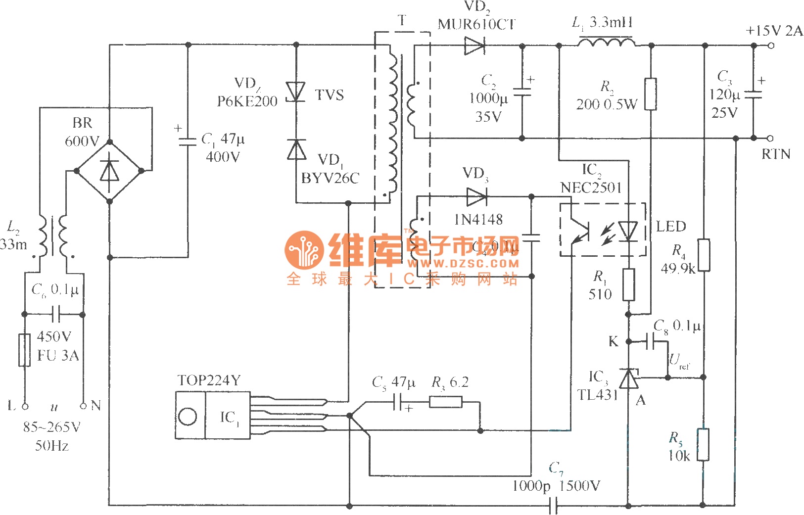
This document presents a 30W micro switch regulated power supply utilizing the TOP224Y integrated circuit. The circuit diagram illustrates its design. A notable feature of this power supply is the use of the TL431 component to replace the regulation...

The circuit depicted in Figure 3-171 includes an auxiliary power supply that operates on single-phase AC power. It features a single-phase half-wave controlled bridge composed of diodes VD7, VD8, and thyristors V1, V2. The output current is managed by...
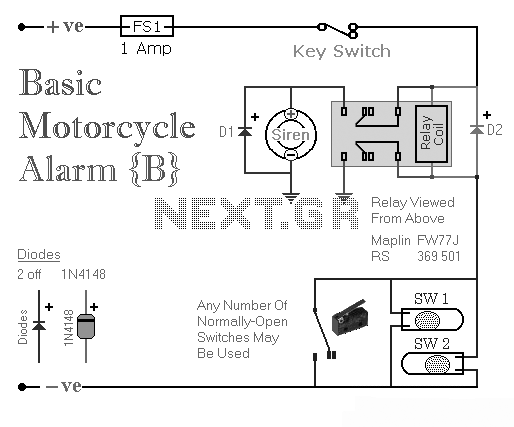
Two simple relay-based motorcycle alarm circuits. These are easy to build and can be used to protect motorcycles, but they also have many other applications. If relays with 6-volt coils are used... The motorcycle alarm circuits described consist of two...

The circuit diagram of this LM317 power supply electronic project requires a few external components. The input voltage for this project must be between 8 and 35 volts, providing a variable output voltage ranging from 1.8 volts to 32...
Supply it with a Li-Ion cell, which has a voltage range of 2.7 to 4.2V. The complexity of a buck/boost converter is not desired. While it is possible to regulate the voltage down to anything below 2.5V, it would...
Warning: include(partials/cookie-banner.php): Failed to open stream: Permission denied in /var/www/html/nextgr/view-circuit.php on line 713
Warning: include(): Failed opening 'partials/cookie-banner.php' for inclusion (include_path='.:/usr/share/php') in /var/www/html/nextgr/view-circuit.php on line 713