
500 metre radio data link
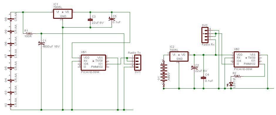
The circuit design involves the integration of a PICAXE microcontroller, which serves as the core processing unit for both the transmitter and receiver. The transmitter circuit consists of a PICAXE chip connected to a 315 MHz or 433 MHz RF module. The microcontroller is programmed to read sensor data, which could include analog voltage levels from a water tank or vehicle detection sensors. Upon detecting a significant change in voltage or a vehicle's presence, the PICAXE activates the RF module to transmit the data packet containing the unique identifier of the transmitter.
The receiver circuit also incorporates a PICAXE microcontroller paired with an RF module capable of receiving the transmitted signals. The receiver is programmed to listen for incoming data packets, decode the unique ID, and perform actions based on the received information, such as logging data or triggering alerts.
To improve transmission reliability, a dipole antenna is constructed, which is tuned to the operating frequency of the RF module. The coaxial cable used to connect the RF module to the antenna helps to minimize interference from the RF signals. Additionally, using a proper power supply for the PICAXE chips and RF modules ensures stable operation and reduces the likelihood of resets due to voltage fluctuations.
In summary, this circuit design allows for effective remote monitoring of water levels or vehicle presence without the complications of wired connections, leveraging the capabilities of PICAXE microcontrollers and RF communication technology. The implementation is adaptable to various applications, ensuring flexibility in monitoring and control systems.Have a water tank you want to measure or a dam or a gate Want to detect a car coming down the drive but don`t want to string wires through the garden This instructable shows how to send data 500 metres with 100% reliability using picaxe microcontroller chips and 315Mhz or 433Mhz radio modules. The transmitter and receiver circuits are quite simple and use picaxe chips. These single chip microcontrollers can sense analog voltages, turn things on and off and can transmit data. See instructables and for a description of how to program picaxe chips. With a radio link as well as an interface to a PC it is possible to sense data remotely and transmit it anywhere in the world. The transmitter prototype was built on a piece of prototype board. There are a myriad of low power 10mW RF modules available which work well up to a range of about 30 metres.
However, once the power goes up above half a watt the RF tends to get back into the picaxe chip and cause resets and other strange behaviour. The answer is to remove the module`s antenna and take the RF away with 3 metres or more of 50ohm coax and build a proper dipole antenna.
This also boosts the range considerably. I`m trying to use a number of xtmr`s with PICAXE chips providing unique IDs to a single RCVR PICAXE combination. All I need is one XTMR on at a time. Once the ID has been received, the receiver needs to listen for another XTMR`s unique ID Good question!
I think the newer picaxes get around a serial hang, but the older ones are already hanging when a serin instruction is run. So it is stuck and won`t go any further until it gets the header. There will be noise but it doesn`t matter so much as the pic doesn`t have any other tasks to do until a packet is received.
I did find this a bit of a limitation though, and have moved a lot of my projects over to the propeller chip, which has 8 cores running in parallel, so you can have one core dedicated to serial comms and still have lots of other things going on at the same time. Cheers, James Yes it probably would. Since I wrote this, other solutions have become available. One of the problems with this design is that it may exceed the legal RF power allowed in your country.
Given this is generally limited to 10mW, the other solution is to increase the receiver sensitivity. I`ve been using this one lately as it has can go to 9600 baud, has a higher Rx sensitivity, has an inbuilt 256 byte buffer, and it seems to be a lot more reliable. If you want to pursue this further please let me know and I`ll try to find a supplier. It seems that the link is broken. For anyone wanting to find the eBay store listed I think it is. They have a page that is just about their radios, find it here. The radios do seem pretty cheap, thanks for pointing them out Mr. Moxham! But no you can`t connect it like you say, because the computer RS232 goes from -12V to +12V, and the module expects 0V to 5V.
You need a max232 chip and then an inverter gate eg 74HC04. At the other end though, yes you can go from the RF receiver straight into a picaxe. The technology has been racing ahead in the last 12 months with more and more RS232 to wireless modules coming out at very good prices. Hope and Yishi are two companies making them for a very good price - probably less than the cost of bare RF modules and a picaxe.
See my post from 3rd April below. Also (sorry for double posting) from what i understand from stuff like this is that its sending machine code 00111011 threw the rf modules couldn`t one just build a Am or/Fm trasmitter and connect it up If you want very simple commands, then the e-madeinchn people have boards with relays on them. Push one of 4 buttons, and one of 4 relays closes. This could be the easiest to configure and I`ve got one and it does have a long range. Or hack a radio control car and use the servo to turn things on and off. How many things do you want to turn on and off and how much data 🔗 External reference
Related Circuits
The AmpLoadPull project demonstrates the utilization of the AmpLoadPull and LoadPullSetup components in Advanced Design System (ADS). These components are part of the ADS behavioral model suite located within the System - Data Models palette. The schematic "circuit_level_amplifier_1_tone.dsn" represents...
The receiver is a triple superheterodyne receiver with two phase-locked loop (PLL) guided local oscillators. The first local oscillator (LO) operates at 2.1 GHz and can be adjusted in increments of 500 kHz, down-converting the received signal to a...
Crystal radios do not require external power sources to operate; they rely solely on radio waves. The first crystal set constructed was a "variometer" radio, which features a larger coil that slides over a smaller coil to modify the...
When the circuit is connected to hi-fi equipment or at both ends of the electronic instrument's speaker, the audio level can be modulated to a 500W lamp proportionally. This is achieved using three appropriate sets of audio filters and...
The circuit below demonstrates how to construct a DAQ_LITE device, accompanied by an image of the finished PCB board. It is important to note that the 80mA fuse depicted in the image and the nearby protection diode are recommended...
The Poppet is a half-watt AM transmitter designed by Mr. Doug Gibson of England. The original design was published in issue 84 of SPRAT, the newsletter of the GQRP Club. The version presented here incorporates modifications suggested by Steve...