
My Crystal Radio Page
The crystal radio designs described utilize fundamental principles of radio frequency reception, leveraging the natural energy of radio waves. The variometer design exemplifies innovative tuning methods by adjusting inductance rather than capacitance. The dual-coil configuration enhances selectivity, allowing for clearer reception of desired signals. The choice of materials, such as PVC for the coil forms, contributes to the durability and effectiveness of the design.
The incorporation of a one-transistor amplifier highlights the importance of amplification in fringe reception areas, where signal strength is weak. The performance discrepancies between the 2N217 and CK722 transistors indicate the necessity of matching components to the original design specifications. Adjustments to bias and voltage are critical in optimizing transistor performance, particularly in audio applications where clarity and volume are paramount.
The slider set presents a more straightforward approach to crystal radio construction, demonstrating that effective designs can be achieved with fewer components. The use of a wooden coil form not only simplifies the assembly process but also impacts the radio's performance characteristics.
The third project illustrates the challenges of integrating salvaged components into new designs. The ferrite coil and variable capacitor configuration is a common approach in crystal radios, but the choice of enclosure can significantly affect performance. The issues faced with the Altoids tin highlight the sensitivity of radio components to their environment, particularly regarding electromagnetic interference.
Overall, these projects reflect a blend of creativity, resourcefulness, and technical understanding, demonstrating the enduring appeal of crystal radio construction as both an educational and practical endeavor in the field of electronics.Crystal radios require no outside sources of power to operate, just the radio waves themselves. The first crystal set I built was a "variometer" radio. In this design, one larger coil slides over a smaller coil to change the coil`s inductance, eliminating the need for avariable capacitor. The radio I`m building has two smaller coils, making it more selective ( ). I got the design from the May 1995 issue of Popular Electronics. The coil forms are made from PVC pipe. The smaller, longer coil which holds the two smaller coils is 8 inches long and 1 inch inside diameter. The shorter, larger coil which slides over the other pipe is 3 inches long and 1. 5 inches inside diameter. The other components are installed using a long terminal strip. At first the radio didn`t work because the detector diode, which should be a 1N34 germanium diode, was a Zener diode.
Luckily, someone sent me some 1N34A germanium diodes, and now it works fine. Since I live in a "fringe" area for AM signals and my only set of high-impedance headphones has an intermittent connection in the "junction box" where the headphone cord is split to the two `phones, I`ve added an onboard one-transistor amplifier, whose design I found in the Boys Second Book of Radio and Electronics. Unfortunately, it has some problems. When using a crystal earphone as a microphone, the output is soft and unintelligible. The problem could lie with the transistor, since I`m using a 2N217 (ECG102A) when the original circuit calls for a CK722 (ECG102).
The ECG102A is a more rugged version of the ECG102, but the voltages are different. Reducing the bias( ) resistor from. 39 Meg to 27K and doubling the voltage from 3V to 6V hasn`t made a difference. A schematic for both can be found below. My second crystal radio is a much-simpler "slider" set. This type of crystal set uses a single coil and a "slider, " which is a piece of metal which slides over the tuning coil to tune the radio. Like my other crystal set, all the parts are mounted on a terminal strip. Unlike my other crystal set, this one uses a square wooden coil form mounted diagonally. I found the design for this set in The Boys First Book of Radio and Electronics. This radio worked on the first try. This surprised me since the coil, which called for 130 feet of 26-gauge wire, has roughly 51 feet of 22-gauge wire (I had no 26-gauge wire so I used what I had, which was 22-gauge wire).
This crystal set isn`t quite as selective as it could be, but it works just as well as my variometer crystal set (possibly better). A schematic of this set can be found below. My third crystal radio project is a simple ferrite coil and variable capacitor design. I was originally planning to build this radio in an "Altoids" mints tin. I salvaged the coil and variable capacitor from a failed AM/FM radio kit I once tried to build. The FM section, which came on a prebuilt circuit board, would tune from what I believe is below the FM broadcast band to the very beginning of it, while the AM section, which didn`t even have a detector diode, would only get one station, with the tuning capacitor only varying the volume of the station.
Instead of the 2SC transistor-based "preamplifier" the AM section of the AM/FM radio kit used, which I suspect is what caused the tuning problem, I`m going to be using a true detector diode. I was hoping the metal tin wouldn`t cause problems with the antenna coil. Unfortunately, mounting the ferrite coil in the tin seemed to be causing the coil to act like a wavetrap, blocking AM signals and only allowing shortwave signals (I was surprised to hear CBC and BBC World Service drifting in and out of my headphones).
Also, the variable cap did nothing, and it got two or more signals at once. I transplanted the innards to a Radio Shack plastic enclosure, hoping it would fix the problem, but it didn`t ch 🔗 External reference
Related Circuits
This circuit utilizes a ceramic tuning resonator with a frequency of 3.587 MHz, alongside resonator filters available at frequencies of 5.5 MHz, 7.7 MHz, and 10.7 MHz. The transmission range of the device is approximately 2-4 km. The circuit...
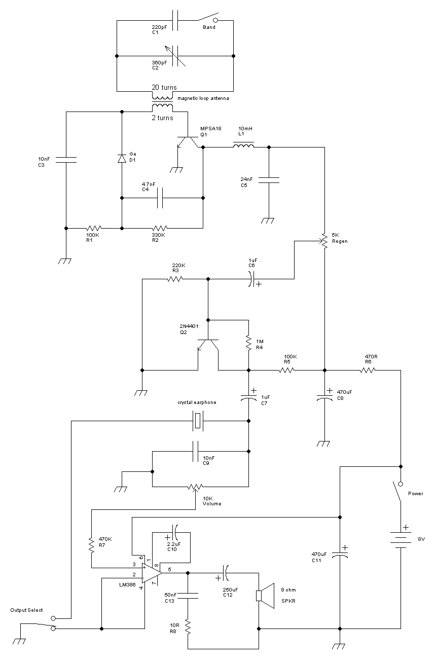
This receiver is a modification of Charles Wenzel's Two Transistor Reflex Radio. Instead of a ferrite AM loopstick antenna, a magnetic loop antenna is used, and an LM386 amplifier stage has been added to drive an 8-ohm speaker. A...
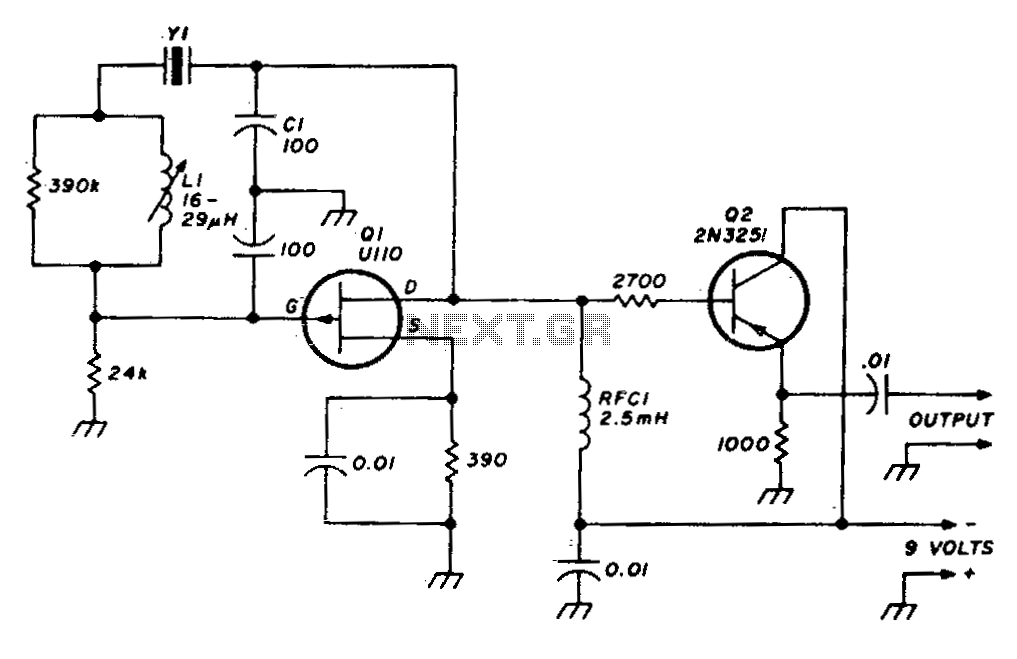
A stable variable crystal oscillator (VXO) utilizing 6- or 8-MHz crystals employs a capacitor and an inductor to facilitate frequency pulling on either side of series resonance. The described circuit operates as a variable crystal oscillator, which is crucial in...
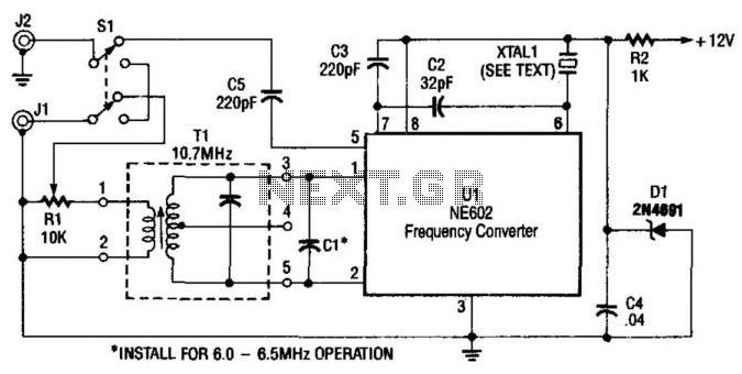
A Signetics NE602 is utilized in this converter to tune the frequency range of 9.5 to 9.8 MHz. An AM car radio functions as a tunable intermediate frequency (IF) amplifier, with the output being taken from J2, the auto...
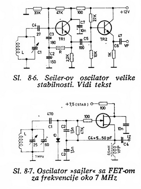
Will an LC-based oscillator be able to demonstrate performance comparable to crystals under such conditions (possibly in unusual configurations like LC-opamp) so that any energy loss at each stage is recovered, resulting in a narrower bandwidth? Examine some amateur...
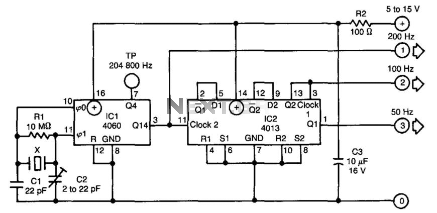
The time base circuit described above generates 50, 100, or 200 Hz signals using an inexpensive crystal oscillator cut for 3.2768 MHz, which is commonly utilized in microprocessor applications. The circuit operates on a power supply range of 5...
Warning: include(partials/cookie-banner.php): Failed to open stream: Permission denied in /var/www/html/nextgr/view-circuit.php on line 713
Warning: include(): Failed opening 'partials/cookie-banner.php' for inclusion (include_path='.:/usr/share/php') in /var/www/html/nextgr/view-circuit.php on line 713