
light weight data capture and signal generator

The DAQ_LITE circuit is designed for data acquisition purposes, leveraging the capabilities of the PIC18F4620 microcontroller. This microcontroller is equipped with multiple analog-to-digital converters (ADCs) that facilitate the conversion of analog signals into digital data, which can then be processed or transmitted to a computer for analysis.
The PCB layout should be carefully designed to accommodate the microcontroller, necessary passive components, and the recommended fuse and diode. The fuse serves as a protective measure against overcurrent conditions, while the diode provides reverse polarity protection, ensuring the circuit operates safely under varying input conditions.
The programming of the PIC18F4620 microcontroller is a critical step. The MPLAB project files, which are provided, include the necessary firmware to configure the microcontroller's ADC settings, communication protocols, and data handling routines. The PICkit programmer facilitates the uploading of this firmware to the microcontroller, enabling it to perform its intended functions effectively.
Connections for the PICkit 2 programmer are essential for programming the microcontroller. These connections typically include the MCLR (Master Clear), VDD (supply voltage), VSS (ground), and data lines for programming. Proper attention to these connections is crucial for successful programming and operation of the DAQ_LITE circuit.
Overall, the DAQ_LITE circuit is a versatile and efficient solution for data acquisition applications, providing a foundation for further development and integration into larger systems.The circuit below illustrates how to build your own daq_lite - also shown is a photo of a completed PCB board. Note that the 80mA fuse shown in the photo and the protection diode close to it are recommended but not necessary.
Once you`ve built the circuit you`ll need to program the PIC18f4620 microcontroller to set it up to read and write to/from a computer - MPLAB project files are availble here for this purpose. Note that you`ll need a PicKit programmer to porgamme the PIC18f4620 - the PicKit2 connections shown in the schematic are required solely for this purpose. 🔗 External reference
Related Circuits
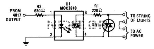
This circuit enables a CMOS logic chip, such as a 4017 decode driver, to control a string of Christmas lights or other lighting. The triac should be rated at 200 V and 3 A or higher. The 4017 should...
The circuit diagram of an IC Controlled Emergency Light with Charger, also known as a 12V to 220V AC inverter circuit, is presented here. This circuit features automatic activation of the light during mains failure and includes a battery...
A battery-powered light control circuit is designed to delay the lighting of a small lamp during sudden power outages or nighttime situations when a blown fuse leaves a room in darkness. This circuit addresses the difficulty of locating matches...
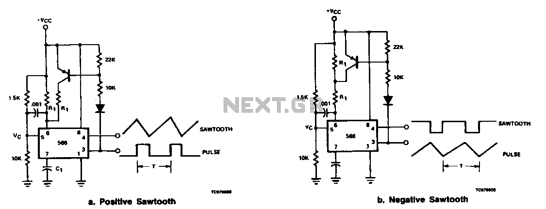
The output at pin 3 of the 566 can be utilized to deliver varying charge and discharge currents for capacitor Cl, resulting in a sawtooth waveform available at pin 4 and a pulse output at pin 3. It is...
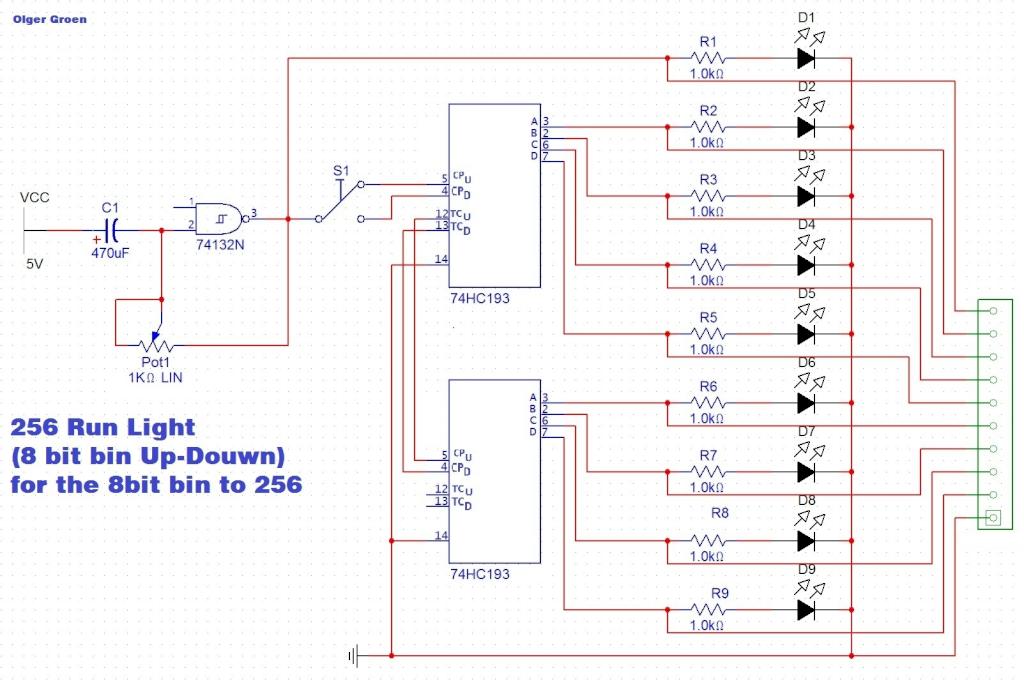
Switch S1 allows for direction change (Up/Down), Pot1 adjusts the clock speed, and LED D1 serves as an indicator for the clock speed. The circuit utilizes a switch (S1) to control the direction of operation, allowing for two modes: upward...
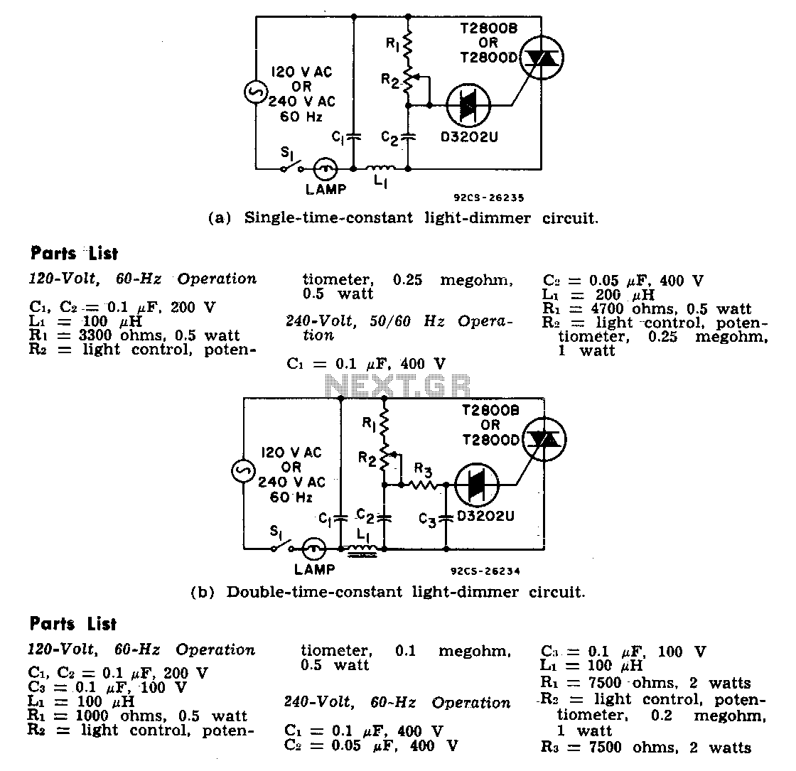
The two lamp-dimmer circuits differ in that one employs a single-time-constant trigger network, while the other uses a double-time-constant trigger circuit. This second configuration reduces hysteresis effects and extends the effective range of the light-control potentiometer. Hysteresis refers to...