
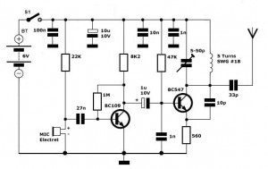
the Poppet 500 milliwatt AM transmitter

The Poppet AM transmitter circuit is a compact and efficient design suitable for hobbyists and those interested in low-power broadcasting. The primary component of this circuit is the LM386 audio amplifier, which serves as the modulator. This chip is capable of delivering sufficient power to drive the output transistor, which further amplifies the signal for transmission. The output stage typically utilizes a transistor that can handle the required power levels, ensuring that the transmitter operates effectively within the designated frequency range.
For optimal performance, it is crucial to ensure that the LM386 and the output transistor are equipped with appropriate heatsinks to prevent overheating during extended operation. The "dead bug style" construction allows for a more compact layout and effective thermal management, as the modulator chip is mounted directly to the copper board, enhancing heat dissipation.
To facilitate operation in the AM broadcast band, the Poppet can be easily modified. Increasing the capacitance of capacitor C8 will lower the frequency of the voltage-controlled oscillator (VFO), allowing the transmitter to operate within the desired 1600-1720 kHz range. Alternatively, replacing the VFO with a crystal oscillator or a phase-locked loop (PLL) synthesizer can provide a more stable frequency source, which is particularly beneficial for consistent transmission quality.
When using the Poppet with a line-level audio source, such as a mixer or tape player, the microphone preamp stage can be omitted, simplifying the overall design. This flexibility in input options makes the Poppet a versatile transmitter suitable for various applications, including neighborhood broadcasting and experimental radio projects. Overall, the Poppet embodies a practical approach to AM transmission, combining ease of construction with the potential for significant customization.The Poppet" is a half-watt AM transmitter designed by Mr. Doug Gibson of England. The original design was published in issue 84 of SPRAT, newsletter of the GQRP Club. The version shown here incorporates changes suggested by Steve Hartley and others. Although it was designed to work with a microphone and to be used in the 160 meter band (1800-2000 kHz), the Poppet can easily be modified to work in the 1600-1720 kHz end of the AM broadcast band and work with a line level input from a mixer instead of a microphone. Construction details are not critical. The LM386 and the output transistor will need heatsinks. The circuit can be built "dead bug style" with the modulator chip stuck upside-down to the copper circuit board for heatsinking.
To modify the Poppet for neighborhood broadcasting in the 1600-1720 kHz frequency range, either increase the capacitance of C8 to bring the VFO`s frequency down into the broadcast band, or replace the VFO with a simple crystal oscillator or PLL synthesizer. The microphone pre-amp stage can be omitted if the unit is used with a line-level audio source such as a mixer or tape player.
🔗 External reference
Related Circuits
This infrared transmitter utilizes pulse width modulation (PWM). The transmitter is equipped with an LM567 tone decoder circuit. An audio signal (at least 50 mV peak-to-peak) is amplified with transistor T1 and subsequently used to modulate IC1. The frequency...
This schematic represents an FM transmitter that delivers an output power of 3 to 3.5 watts, operational within the frequency range of 90 to 110 MHz. While the stability of the circuit is acceptable, incorporating a Phase-Locked Loop (PLL)...
Simple FM Transmitter Circuit This simple FM transmitter circuit was built using a transistor with a transmission distance of about 300m around your home. The simple FM transmitter circuit utilizes a transistor to modulate audio signals onto a radio frequency...
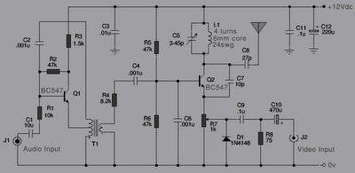
The following is a series of simple TV transmitters utilizing negative sound modulation and PAL video modulation. This design is suitable for countries employing TV systems B and G. Inductor L1 can be constructed using 24 SWG wire, consisting...

This design outlines a tracking transmitter for audio tones operating in the FM band frequency. The circuit can function as either a signal transmitter or a remote control transmitter and utilizes only readily available components. It has a transmission...
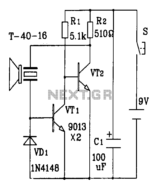
The discrete components ultrasonic transmitter circuit T/R-40-16 can emit a series of ultrasonic signals at a frequency of 40 kHz. This circuit operates at a voltage of 9V and has a current consumption of 25mA, with a control distance...