
500 mW VHF Video Transmitter

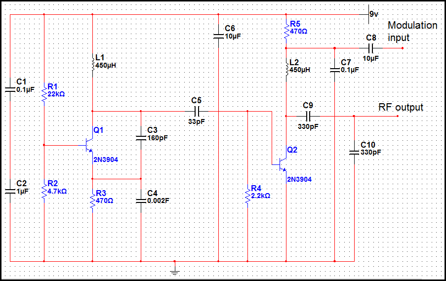
The tuned circuit described utilizes a combination of capacitors and inductors to achieve resonance at a specific frequency, which is crucial for effective signal transmission and reception. The components C4, L1, C8, and L3 are carefully selected to form a resonant tank circuit, with the trimmer capacitors providing fine-tuning capabilities to adjust the circuit's operating frequency. This ensures optimal performance in the desired frequency range, particularly for security monitoring applications where reliability and precision are paramount.
The choice of NPN transistors, such as the BC54 and 2N3642, offers flexibility in component selection, allowing for variations based on availability and performance characteristics. These transistors are known for their suitability in RF applications, providing sufficient gain and frequency response for the circuit's needs.
The absence of audio components simplifies the design, focusing on RF signal processing. This streamlined approach is beneficial for security monitoring systems, where audio signals are not required, and the emphasis is on detecting and transmitting RF signals effectively. The mention of the RF coupling transformer highlights the potential for expansion should audio capabilities be needed in future iterations of the design.
The use of the 2N4427 transistor for the output stage (Q2) is noteworthy due to its capability to handle high power levels, specifically up to 1 Watt at VHF frequencies. The recommendation for a heat sink is critical, as high-power transistors can generate significant heat during operation, which, if not dissipated, could lead to thermal runaway and eventual failure of the component. Connecting a dummy load or antenna is essential for safe operation; without it, the circuit may experience undesired behavior or damage when powered on.
In summary, this tuned circuit design is well-suited for security monitoring applications, leveraging a straightforward architecture and robust components to achieve effective RF performance while maintaining the option for future enhancements.Tuned circuits consist of C4, L1, C8, L3, and the two 15 pF trimmer capacitors across the collectors and emitters of both transistors. Other NPN transistors like BC54, 2N3642, 43, etc should also work. The circuit is designed for simplicity, so No Audio has been included as this would involve adding at least an RF coupling transformer.
The main use for this circuit is for Security Monitoring . If you use a 2N4427 or similar transistor for Q2 (output), you must use a heat sink. The 2N4427 is capable of delivering 1 Watt of RF at VHF frequencies so be sure that either a 50-75 Ohm dummy load or antenna is connected at all times before applying power. 🔗 External reference
Related Circuits
This transmitter is basic but allows the transmission of audio to an AM radio. It consists of an RF oscillator operating in the AM broadcast band, along with a modulator stage that mixes the incoming audio with the RF...

Most consumer electronic devices utilize infrared remote controls for convenient operation. The carrier frequency of these remote controls typically ranges from 36 kHz to 38 kHz. Control codes are transmitted to the device's receiver in a serial format, which...
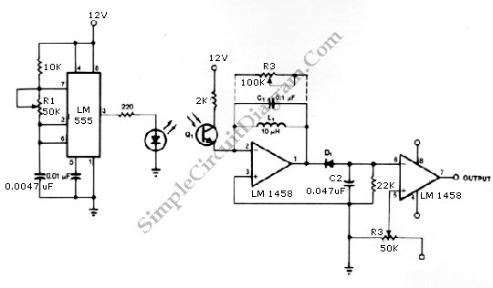
The infrared transmitter and receiver circuit depicted in the schematic diagram can function as a remote control. The transmitter operates as an oscillator circuit, with the frequency adjustable via the R1 potentiometer (or trimmer pot). This oscillation ensures that...
The video amplifier depicted in the diagram is a widely recognized design that is both simple and highly effective. However, the transistors are susceptible to damage if the potentiometers (black level and signal amplitude) are set to their extreme...
This circuit combines horizontal synchronization (H sync), vertical synchronization (V sync), and the actual video signal. Transistor T2 is responsible for mixing the synchronization signals, while transistor T1 functions as an emitter-follower. Typical bandwidths for this circuit can reach...
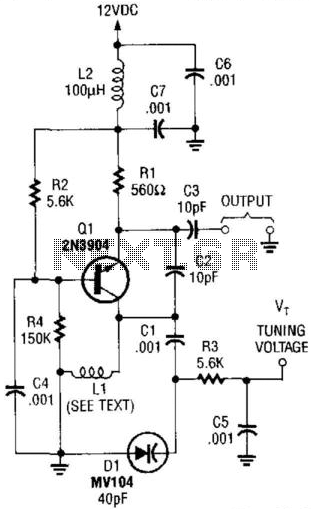
This VHF VCO circuit operates within the frequency range of 30 to 200 MHz. Q1 may be substituted with a 2N3563 for frequencies exceeding 100 MHz. The inductor, L1, is selected to resonate at the desired frequency in conjunction...