
HIGH PERFORMANCE VIDEO MIXER
The described circuit is a fundamental component in video processing, particularly in the context of analog video systems. The integration of H sync, V sync, and video signals is crucial for maintaining proper synchronization between the displayed image and the video source.
Transistor T2 plays a pivotal role in the mixing process, where it combines the synchronization signals to ensure that the timing of the video display aligns accurately with the incoming video data. This mixing is essential for preventing issues such as tearing or misalignment in the displayed image.
Transistor T1, acting as an emitter-follower, provides a high input impedance and low output impedance, which is beneficial for buffering the mixed signal. This configuration allows the circuit to drive subsequent stages without loading down the previous stage, thus preserving signal integrity. The emitter-follower configuration is advantageous in applications where signal isolation is necessary, and it helps to maintain the fidelity of the video signal.
The circuit's bandwidth capability of up to 25 MHz indicates its suitability for standard video resolutions, making it effective for various applications including television broadcasting and video conferencing systems. The design considerations for achieving this bandwidth include careful selection of components and layout to minimize parasitic capacitance and inductance, which can adversely affect performance.
Overall, this circuit exemplifies a critical aspect of video signal processing, where synchronization and signal integrity are paramount for delivering high-quality video output.This circuit mixes H synch. V synch. and actual video. T2 mixes the synch, while T1 serves as an emitter-follower. Bandwidths of up to 25 MHz are typical for this circuit. 🔗 External reference
Related Circuits
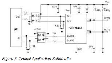
An integrated solution for two output channels that simplifies design and enhances reliability. The device, the VNI2140J, integrates on-chip two 45V Power MOSFET channels with a typical Rds(on) of 80mOhm at 25 degrees Celsius. The VNI2140J is a highly integrated...
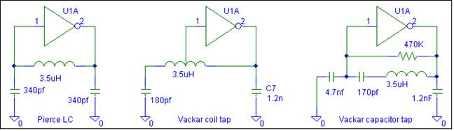
This oscillator does not require biasing components. Only an inductor and various matching or tuning capacitors are needed to set the operating frequency. The active component is the 74HCU04 hex inverter, with only one of the six inverters necessary...
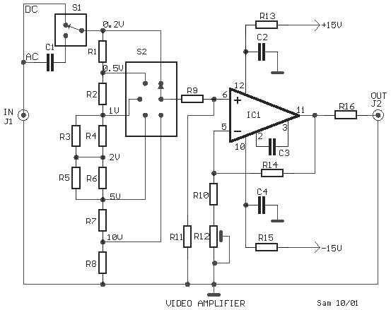
This is a schematic diagram of a video amplifier circuit, built using the very high-speed operational amplifier IC LH0032. Parts List: R1 = 15KΩ, R2, R3, R4 = 10KΩ, R5, R6, R7, R8, R9 = 1KΩ, R10 = 820Ω,...
This is a light dimmer circuit. It does not include any special features and is a typical TRIAC-based dimmer circuit. This circuit is designed to operate with... A TRIAC-based light dimmer circuit is a common electronic design used to control...
A distribution substation is defined by the apparent power of the transformer and its configuration, which can be aerial, terrestrial, or underground. A distribution substation plays a critical role in the electrical power distribution network. It serves as a point where...
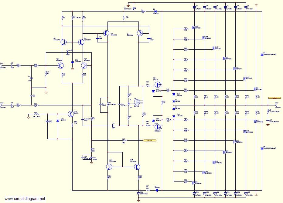
This amplifier is suitable for various applications that demand high power, low noise, minimal distortion, and superior sound quality. Examples include subwoofer amplifiers, front-of-house (FOH) stage amplifiers, and individual channels of high-powered surround sound amplifiers. For a detailed explanation...
Warning: include(partials/cookie-banner.php): Failed to open stream: Permission denied in /var/www/html/nextgr/view-circuit.php on line 713
Warning: include(): Failed opening 'partials/cookie-banner.php' for inclusion (include_path='.:/usr/share/php') in /var/www/html/nextgr/view-circuit.php on line 713