
500w power inverter circuit diagram based tip35c

The circuit primarily consists of a variable resistor, which allows for fine-tuning of the output frequency of the inverter. This adjustment is essential for applications that require precise frequency control, such as motors or other AC devices that may operate optimally at different frequencies.
The variable resistor is connected in a manner that influences the timing of the oscillation within the inverter circuit. When the resistance is altered, it changes the charge and discharge times of capacitors in the circuit, thereby affecting the frequency of the output waveform. A frequency meter is recommended for accurate measurement during adjustments, ensuring the output frequency is set to the desired level.
Safety precautions are paramount when operating this inverter circuit. The warning against powering devices before frequency adjustment is critical, as supplying power at an incorrect frequency can lead to overheating and potential failure of both the inverter and connected devices. Proper calibration of the frequency is essential to maintain equipment longevity and reliability.
In summary, this circuit's design emphasizes the importance of precise frequency control through the use of a variable resistor, with additional safety measures to prevent damage during operation.There is certainly only one variable resistance in this circuit diagram which is made use of to adjust frequency of 240V AC output current. It is best to have a frequency meter to adjust this frequency of 50HZ to 60HZ as per your requirement.
Please don`t power up any device using your inverter just before frequency adjustment for the reason that a wrong AC frequency can burn your equipment as well as your inverter.', more= 🔗 External reference
Related Circuits
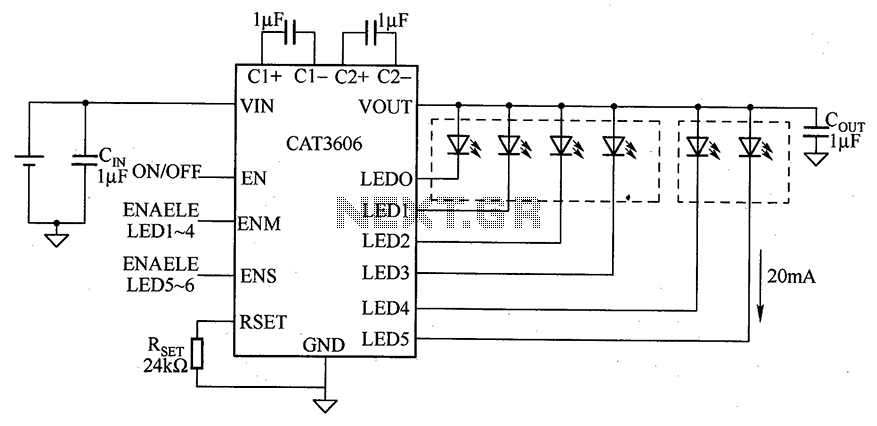
CAT3606 is a high-efficiency white LED driver. This adjustable charge pump is suitable for general-purpose, large-panel, flicker-free white LED backlighting and dual-display systems. The CAT3606 inductor boost circuit can replace conventional high-brightness backlighting requirements, thereby simplifying system design. It...
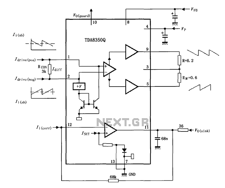
The TDA8350Q test circuit includes a push-pull amplifier configuration where the output terminal resistor serves as a dummy load for testing an alternative deflection coil. The TDA8350Q is a high-performance integrated circuit designed for use in television and display systems....
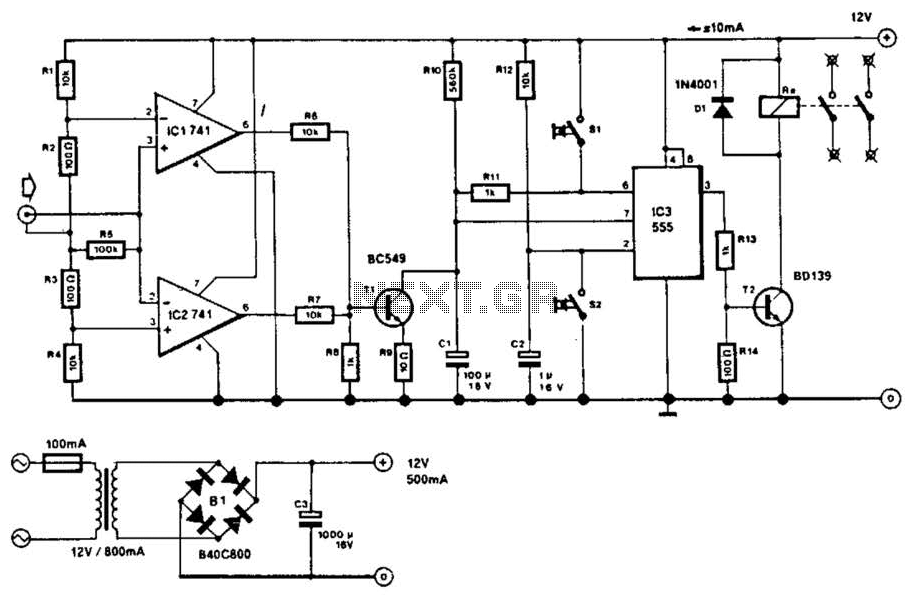
This circuit will disconnect the line supply to audio or video equipment if there has been no input signal for approximately 2 seconds. Switch SI provides manual operation, while switch S2 functions as a reset mechanism. This circuit allows...
To construct the circuit, follow the provided schematic. If assistance is required, do not hesitate to reach out for support. If there are difficulties in identifying the components... To build the circuit effectively, it is essential to adhere closely to...
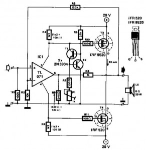
This audio power amplifier employs two complementary MOSFETs (IRF9520 and IRF520) to provide up to 20W output into an 8-ohm speaker. A TL071 operational amplifier functions as the input amplifier. The MOSFETs require heatsinking with a thermal resistance of...
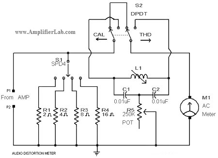
A circuit diagram of an audio distortion meter is presented here. An audio distortion meter is utilized to measure Total Harmonic Distortion (THD). The audio distortion meter is an essential tool in audio engineering, designed to quantify the level of...